
Requirements on the Switchgear
Here what’s important when you’re designing the low voltage switchgear:
- Device Application in the Supply Circuit
- Short-circuit strength
- Release (Trip Unit)
- Device Application in Supply Circuits (Coupling)
- Device Application in the Distribution Circuit
- Device Application in the Final Circuit
1. Device Application in the Supply Circuit
The system infeed is the most “sensitive” circuit in the entire power distribution. A failure here would result in the entire network and therefore the building or production being without power. This worst-case scenario must be considered during the planning.
Redundant system supplies and selective protection setting are important preconditions for a safe network configuration. The selection of the correct protective devices is therefore of elementary importance in order to create these preconditions.
Some of the key dimensioning data is addressed in the following:
1.1 Rated current
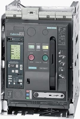
The feeder circuit-breaker in the Low-voltage main distribution (LVMD) must be dimensioned for the maximum load of the transformer/generator. When using ventilated transformers, the higher operating current of up to 1.5 x IN of the transformer must be taken into account.
2. Short-circuit strength
The short-circuit strength of the feeder circuit-breaker is determined by (n–1) x Ik max of the transformer or transformers (n = number of transformers).
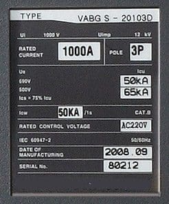
This means that the maximum shortcircuit current that occurs at the installation position must be known in order to specify the appropriate short-circuit strength of the protective device (Icu).
2.1 Utilization category
When dimensioning a selective network, time grading of the protective devices is essential. When using time grading up to 500 ms, the selected circuit-breaker must be able to carry the short-circuit current that occurs for the set time. Close to the transformer, the currents are very high.
This requirement is satisfied by circuit-breakers of utilization category B (e.g. air circuit-breakers, ACB). Current-limiting circuit breakers (molded-case circuit breakers, MCCB) trip during the current rise. They can therefore be constructed more compactly.
3. The Release (Trip Unit)
For a selective network design, the release (trip unit) of the feeder circuit-breaker must have an LSI (electronic trip unit) characteristic.
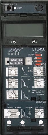
Depending on the curve characteristic of the upstream and downstream protective devices, the characteristics of the feeder circuit breaker in the overload range (L) and also in the time-lag short circuit range (S) should be optionally switchable (I4t or I2t characteristic curve).
This facilitates the adaptation of upstream and downstream devices.
3.1 Internal accessories
Depending on the respective control, not only shunt releases (previously: f releases), but also undervoltage releases are required.
3.2 Communication
Information about the current operating states, maintenance, error messages and analyses, etc. is being increasingly required, especially from the very sensitive supply circuits. Flexibility may be required with regard to a later upgrade or retrofit to the desired type of data transmission.
4. Device Application in Supply Circuits (Coupling)
If the coupling (connection of Network 1 to Network 2) is operated open, the circuit-breaker (tie breaker) only has the function of an isolator or main switch. A protective function (release) is not absolutely necessary.
The following considerations apply to closed operation:
4.1 Rated current
Must be dimensioned for the maximum possible operating current (load compensation). The simultaneity factor can be assumed to be 0.9.
4.2 Short-circuit strength
The short-circuit strength of the feeder circuit-breaker is determined by the sum of the short-circuit components that flow through the coupling. This depends on the configuration of the component busbars and their supply.
4.3 Utilization category
As for the system supply, utilization category B is also required for the current carrying capacity (Icw value).
4.4 Release
Partial shutdown with the couplings must be taken into consideration for the supply reliability. As the coupling and the feeder circuit-breakers have the same current components when a fault occurs, similar to the parallel operation of two transformers, the LSI characteristic is required.
5. Device Application in the Distribution Circuit
The distribution circuit receives power from the higher level (supply circuit) and feeds it to the next distribution level (final circuit).
The specifications for the circuit dimensioning must be fulfilled. The ACB has advantages if full selectivity is required. However for cost reasons, the ACB is only frequently used in the distribution circuit as of a rated current of 630 A or 800 A. As the ACB is not a current-limiting device, it differs greatly from other protective devices such as MCCB, MCB and fuses.
As no clear recommendations can otherwise be given, Table 1 shows the major differences and limits of the respective protective devices.
6. Device Application in the Final Circuit
The final circuit receives power from the distribution circuit and supplies it to the consumer (e.g. motor, lamp, non-stationary load (power outlet), etc.). The protective device must satisfy the requirements of the consumer to be protected by it.
Table 1 – Overview of the protective devices
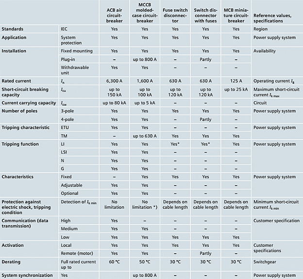
*) with ETU: No limitation / with TMTU: depends on cable length
Reference: Siemens Energy Sector – Power Engineering Guide Edition 7.0








I’m Electrical B tech engineer.
If we design power switchgear with touch systems and also connect it with GSM, And also control with SCADA.
sir please post on electrical design field.