
Estimated Study Time: 4 minutes
Power factor
Should the voltage on a circuit fall below a specified level for some reason, a device called a capacitor can momentarily maintain the voltage at line value. Basically, a capacitor serves the same purpose as a storage tank in a water system.
By maintaining the water in a storage tank at a definite level, the pressure on the water supplied by the system connected to it is maintained evenly.
It is the job of capacitors to keep the power factor as close to 1 as possible.
Capacitance is the enemy of inductance. Therefore, capacitors counteract inductance, keep the power factor close to 1, and save money for the utility company.
The capacitor usually consists of two conductors separated by an insulating substance. Among other materials which may be used, a capacitor can be made of aluminum foil separated by oil-impregnated paper (see Figure 4-22), or synthetic insulating materials.

Capacitance is the property of a capacitor. Capacitance depends on the area of the conductors, on the distance between the conductors and on the type of insulating material used.
Introducing inductance (or an inductor) into a circuit causes the current to lag the voltage in phase. In most power applications, inductance prevails and reduces the amount of pay-load power produced by the utility company for a given size of generating equipment.
The capacitor counteracts this loss of power and makes powerproduction more economical.
 Primary and (b) secondary")
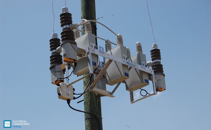
Capacitors are mounted on crossarms or platforms (see Figure 2) and are protected with lightning arresters and cutouts, the same as transformers. Figure 3 illustrates the many uses that are made of capacitors.
How capacitors are used

Reference: Guide to Electrical Power Distribution Systems – Anthony J. Pansini, EE, PE; Life Fellow IEEE, Sr. Member ASTM
Related electrical guides & articles


Edvard Csanyi
Hi, I'm an electrical engineer, programmer and founder of EEP - Electrical Engineering Portal. I worked twelve years at Schneider Electric in the position of technical support for low- and medium-voltage projects and the design of busbar trunking systems.I'm highly specialized in the design of LV/MV switchgear and low-voltage, high-power busbar trunking (<6300A) in substations, commercial buildings and industry facilities. I'm also a professional in AutoCAD programming.
Profile: Edvard Csanyi

I’m thinking utility size and grade capacitors can be used in charging and creating an inverter for solar charged batteries. Li batteries are 2v and are best charged in parallel. Li batteries are best used in series to deliver high voltage (e.g. 400VDC…200 batteries in series). Could a DC/DC converted be configured that uses MOSFETs and/or EGBTs to configure the batteries in parallel for charging. Could other such electronic switches configure the bank in series and switch the batteries to form a 60Hz square wave or pseudo sine wave and use large utility capacitors to filter out harmonics to deliver 60Hz VAC pure sine wave output to a transformer input?
Good interaction