The performance of Electric Motor
As you already know, electric motor is used everywhere in industry and in term of technology – it’s already pretty complex, sometimes making it a challenge to keep it running at peak performance.

It’s VERY important to remember that the causes of motor and drive issues are not confined to a single domain of expertise – both mechanical and electrical issues can lead to motor failure – and being armed with the right knowledge can mean the difference between costly downtime and improved asset uptime.
When electric motor fails – you can do few things, but before motor fails – you can do many many things to suppress eventual failure or heavy damage. Winding insulation breakdown and bearing wear are the two most common causes of motor failure, but those conditions arise for many different reasons.


This technical article is written by Fluke engineers and it demonstrates how to detect the most common causes of winding insulation and bearing failure in advance. They also suggested devices you can use for testing.
- Power Quality
- Variable frequency drives
- Mechanical
- Improper installation factors
At the end of the article as a conclusion, I’ll mention four strategies for success in managing your electric motors.
1. Power Quality
1.1 Transient voltage
Transient voltages can come from a number of sources either inside or outside of the plant. Adjacent loads turning on or off, power factor correction capacitor banks or even distant weather can generate transient voltages on distribution systems. These transients, which vary in amplitude and frequency, can erode or cause insulation breakdown in motor windings.
For example, a transient may appear on control cables that don’t necessarily cause equipment damage directly, but may disrupt operations.


| Impact: | Motor winding insulation breakdown leads to early motor failure and unplanned downtime |
| Instrument to measure and diagnose: | Fluke 435-II Three-Phase Power Quality Analyzer |
| Criticality: | High |
Go back to causes of a motor failure ↑
1.2 Voltage imbalance
Three-phase distribution systems often serve single-phase loads. An imbalance in impedance or load distribution can contribute to imbalance across all three of the phases.
Potential faults may be in the cabling to the motor, the terminations at the motor, and potentially the windings themselves.
This imbalance can lead to stresses in each of the phase circuits in a three-phase power system. At the simplest level, all three phases of voltage should always have the same magnitude.


| Impact: | Imbalance creates excessive current flow in one or more phases that then increases operating temperatures–leading to insulation breakdown |
| Instrument to measure and diagnose: | Fluke 435-II Three-Phase Power Quality Analyzer |
| Criticality: | Medium |
Go back to causes of a motor failure ↑
1.3 Harmonic distortion
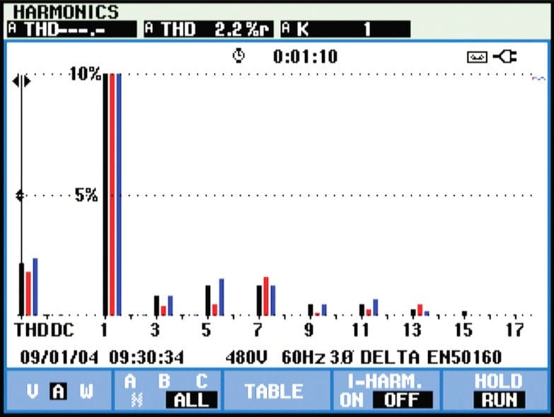
Simply stated, harmonics are any unwanted additional source of high frequency AC voltages or currents supplying energy to the motor windings.
This additional energy is not used to turn the motor shaft but circulates in the windings and ultimately contributes to internal energy losses.
These losses dissipate in the form of heat, which, over time, will deteriorate the insulation capability of the windings. Some harmonic distortion of the current is normal on any part of the system serving electronic loads.
To start investigating harmonic distortion, use a power quality analyzer to monitor electrical current levels and temperatures at transformers to be sure that they are not overstressed. Each harmonic has a different acceptable level of distortion, which is defined by standards such as IEEE 519-2014.


| Impact: | Decrease in motor efficiency results in added cost and an increase in operating temperatures |
| Instrument to measure and diagnose: | Fluke 435-II Three-Phase Power Quality Analyzer |
| Criticality: | Medium |
Go back to causes of a motor failure ↑
2. Variable frequency drives
2.1 Reflections on drive output PWM signals
Variable frequency drives employ a pulse width modulation (PWM) technique to control the output voltage and frequency to a motor. Reflections are generated when there is an impedance mismatch between the source and load.
Impedance mismatches can occur as a result of improper installation, improper component selection or equipment degradation over time. In a motor drive circuit, the peak of the reflection could be as high as the DC bus voltage level.


| Impact: | Motor winding insulation breakdown leads to unplanned downtime |
| Instrument to measure and diagnose: | Fluke 190-204 ScopeMeter fast sampling 4 channel portable oscilloscope |
| Criticality: | High |
Go back to causes of a motor failure ↑
2.2 Sigma current
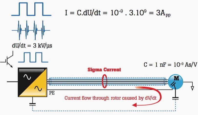
Sigma currents are essentially stray currents that circulate in a system. The sigma currents are created as a result of the signal frequency, voltage level, capacitance and inductance in conductors. These circulating currents can find their way through protective earth systems causing nuisance tripping or in some cases excess heat in windings.
In a perfect situation, the sum of the three currents would equal zero. In other words, the return current from the drive would be equal to the current to the drive. Sigma current can also be understood as asymmetrical signals in multiple conductors that can capacitively couple currents into the ground conductor.


| Impact: | Mysterious circuit trip due to protective earth current flow |
| Instrument to measure and diagnose: | Fluke 190-204 ScopeMeter isolated 4 channel portable oscilloscope with wide bandwidth (10kHz) current clamp (Fluke i400S or similar) |
| Criticality: | Low |
Go back to causes of a motor failure ↑
2.3 Operational overloads
Motor overload occurs when a motor is under excessive load. The primary symptoms that accompany a motor overload are excessive current draw, insufficient torque and overheating.
Excessive motor heat is a major cause of motor failure.
In the case of an overloaded motor individual motor components including bearings, motor windings, and other components may be working fine, but the motor will continue to run hot. For this reason, it makes sense to begin your troubleshooting by checking for motor overload. Because 30% of motor failures are caused by overloading, it is important to understand how to measure for and identify motor overloading.


| Impact: | Premature wear on motor electrical and mechanical components leading to permanent failure |
| Instrument to measure and diagnose: | Fluke 289 Digital Multimeter |
| Criticality: | High |
Go back to causes of a motor failure ↑
3. Mechanical
3.1 Misalignment of a motor
Misalignment occurs when the motor drive shaft is not in correct alignment with the load, or the component that couples the motor to the load is misaligned. Many professionals believe that a flexible coupling eliminates and compensates for misalignment, but a flexible coupling only protects the coupling from misalignment.
In addition, misalignment may feed vibration into both the load and the motor drive shaft. There a few types of misalignment:
- Angular misalignment – Shaft centerlines intersect but are not parallel
- Parallel misalignment – Shaft centerlines are parallel but not concentric
- Compound misalignment – A combination of parallel and angular misalignment.
Note // Almost all misalignment is compound misalignment, but practitioners talk about misalignment as the two separate types because it is easier to correct a misalignment by addressing the angular and parallel components separately.


| Impact: | Premature wear in mechanical drive components that leads to premature failures |
| Instrument to measure and diagnose: | Fluke 830 Laser Shaft Alignment Tool |
| Criticality: | High |
Go back to causes of a motor failure ↑
3.2 Shaft imbalance
Imbalance is a condition of a rotating part where the center of mass does not lie on the axis of rotation. In other words, there is a “heavy spot” somewhere on the rotor. Although you can never completely eliminate motor imbalance, you can identify when it is out of normal range, and take action to rectify the problem.
Imbalance can be caused by numerous factors, including //
- Dirt accumulation
- Missing balance weights
- Manufacturing variations
- Uneven mass in motor windings and other wear-related factors.
A vibration tester or analyzer can help you determine whether or not a rotating machine is in balance.


| Impact: | Premature wear in mechanical drive components that leads to premature failures |
| Instrument to measure and diagnose: | Fluke 810 Vibration Tester |
| Criticality: | High |
Go back to causes of a motor failure ↑
3.3 Shaft looseness
Looseness occurs when there is excessive clearance between parts. Looseness can occur in several places:
- Rotating looseness is caused by excessive clearance between rotating and stationary elements of the machine, such as in a bearing.
- Non-rotating looseness happens between two normally stationary parts, such as a foot and a foundation, or a bearing housing and a machine.
As with all other sources of vibration, it is important to know how to identify looseness and resolve the issue to avoid losing money. A vibration tester or analyzer can determine whether or not a rotating machine is suffering from looseness.


| Impact: | Accelerated wear on rotating components resulting in mechanical failure |
| Instrument to measure and diagnose: | Fluke 810 Vibration Tester |
| Criticality: | High |
Go back to causes of a motor failure ↑
3.4 Bearing wear
A failed bearing has increased drag, emits more heat, and has lower efficiency because of a mechanical, lubrication, or wear problem.
Bearing failure can be caused by several things:
- A heavier load than designed for
- Inadequate or incorrect lubrication
- Ineffective bearing sealing
- Shaft misalignment
- Incorrect fit
- Normal wear
- Induced shaft voltages
13 % of motor failures are caused by bearing failure, and more than 60 % of the mechanical failures in a facility are caused by bearing wear, so learning how to troubleshoot this potential problem is important.


| Impact: | Accelerated wear on rotating components resulting in bearing failure |
| Instrument to measure and diagnose: | Fluke 810 Vibration Tester |
| Criticality: | High |
Go back to causes of a motor failure ↑
4. Improper installation factors
4.1 Soft foot
Soft foot refers to a condition in which the mounting feet of a motor or driven component are not even, or the mounting surface upon which the mounting feet sit is not even.
There are two kinds of soft foot:
- Parallel soft foot – Parallel soft foot occurs when one of the mounting feet sits higher than the other three
- Angular soft foot – Angular soft foot occurs when one of the mounting feet is not parallel or “normal” to the mounting surface.
In both cases, soft foot can be caused either by an irregularity in the machine mounting feet, or in the mounting foundation upon which the feet rest. In either case, any soft foot condition must be discovered and remedied before proper shaft alignment can be achieved. A quality laser alignment tool can typically determine whether or not there is a soft foot problem on a particular rotating machine.


| Impact: | Misalignment of mechanical drive components |
| Instrument to measure and diagnose: | Fluke 830 Laser Shaft Alignment Tool |
| Criticality: | Medium |
Go back to causes of a motor failure ↑
4.2 Pipe strain
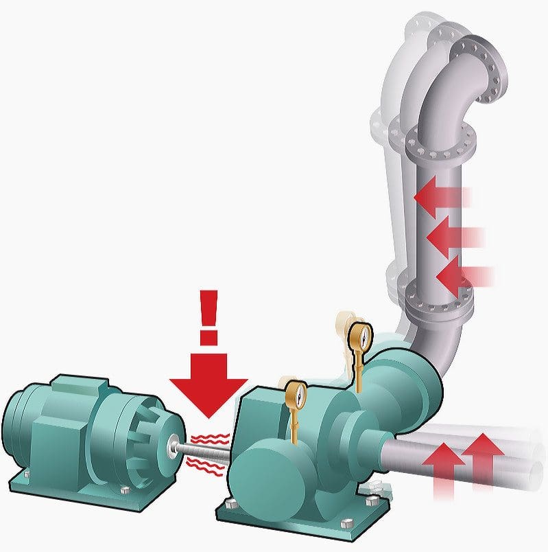
Pipe strain refers to the condition in which new stresses, strains, and forces, acting on the rest of the equipment and infrastructure transfer backward onto the motor and drive to induce a misalignment condition.
The most common example of this is in simple motor/pump combinations, where something applies force to the pipeworks such as:
- A shift in the foundation
- A newly installed valve or other component
- An object striking, bending, or simply pressing on a pipe
- Broken or lack-of pipe hangers or wall-mounting hardware
For this reason it is important to check machine alignment more than just at the time of installation–precision alignment is a temporary condition that can change over time.


| Impact: | Shaft misalignment and subsequent stresses on rotating components, leading the premature failures. |
| Instrument to measure and diagnose: | Fluke 830 Laser Shaft Alignment Tool |
| Criticality: | Low |
Go back to causes of a motor failure ↑
4.3 Shaft voltage
When motor shaft voltages exceed the insulating capability of the bearing grease, flashover currents to the outer bearing will occur, thereby causing pitting and grooving to the bearing races. The first signs of this problem will be noise and overheating as the bearings begin to lose their original shape and metal fragments mix with the grease and increase bearing friction.
Shaft voltage is only present while the motor is energized and rotating. A carbon brush probe attachment allows you to measure shaft voltage while a motor is rotating.


| Impact: | Arcing across bearing surfaces create pitting and fluting resulting in excessive vibration and eventual bearing failure |
| Instrument to measure and diagnose: | Fluke-190-204 ScopeMeter isolated 4-channel portable oscilloscope, with AEGIS shaft voltage carbon brush probe. |
| Criticality: | High |
Go back to causes of a motor failure ↑
What can you actually do?
Four strategies for success
Motor control systems are being utilized in critical processes throughout manufacturing plants. Equipment failure can result in high monetary losses both from potential motor, or parts, replacement and from equipment downtime for the system the motor powers.
There are four key strategies that you can undertake to restore or prevent premature failures in motor drive and rotating component:
- Document operating condition, machine specifications and performance tolerance ranges.
- Capture and document critical measurements at installation, before and after maintenance and on a routine basis.
- Create an archive reference of measure ments to facilitate trend analysis and identify change of state conditions.
- Plot individual measurements to establish a baseline trend. Any change in trend line of more than ±10% to 20% (or any other % determined, based on your system performance or criticality) should be investigated to root cause to understand why the issue is occurring.
Go back to causes of a motor failure ↑
Reference // Application Note by FLUKE – 13 common causes of motor failure


How much normally is the acceptable temperature of a 37-KW 3-phase Squirrel Cage AC Induction Motor particularly used in driving two hydraulic pumps (front & rear) for Baling Machine of Sugar Cane?
Connections: Any time a connection is made a connection can fail. Crimps will loosen over time and cause a high resistance. This can happen over a short or long time. In the end the connection can open circuit. If it’s in close proximity to another phase of the motor both connections could go bad or even short. Screw terminals will loosen and overheat also. Any transition from one wire to another requires a connection. Sometimes those transitions involve aluminum to copper wires. These are inherently unstable interfaces. Steps are taken to prevent oxygen getting to the connection. Sometimes the transition is welded. Any connection involving dissimilar metals will be even more susceptible to failure.
Any heating near plastic insulators will break down this insulation. Leakage current will increase to the housing if that housing is grounded. It should be grounded to reduce the probability of electric shock to operators or service personnel. This is regardless of size. Even fractional horsepower motors driven by line potential can have dangerous leakage current to the chassis. Given high tech motor controls these currents can be high frequency. GFCI’s are designed to be accurate at 60 hz. Other frequencies can falsely trigger GFCI’s. Putting a new one in may not fix it if it’s of the same make. Different manufacturers devices perform differently.