Practical and economical feasibility
It’s important to understand where the capacitors are to be installed for a better exploitation of such advantages. There are no general rules applicable to every type of installation and, in theory, capacitors can be installed at any point, but it is necessary to evaluate the relevant practical and economical feasibility.

According to the location modalities of the capacitors, the main methods of power factor correction are:
- Distributed power factor correction
- Group power factor correction
- Centralized power factor correction
- Combined power factor correction
- Automatic power factor correction
Now, let’s say a word about each of above listed methods…
1. Distributed power factor correction
Distributed power factor correction is achieved by connecting a capacitor bank properly sized directly to the terminals of the load which demands reactive power.
This type of power factor correction is advisable in the case of large electrical equipment with constant load and power and long connection times and it is generally used for motors and fluorescent lamps.

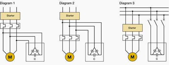
Figure 1 above shows the common connection diagrams for the power factor correction of motors. Let’s explain each of the cases from connection diagrams.
In case of direct connection (diagrams 1 and 2), the following risk may be run: after the disconnection from the supply, the motor will continue to rotate (residual kinetic energy) and self-excite with the reactive energy drawn from the capacitor bank, and may turn into an asynchronous generator. In this case, the voltage on the load side of the switching and control device is maintained, with the risk of dangerous overvoltages (up to twice the rated voltage value).
When using diagram 3, the compensation bank is connected only after the motor has been started and disconnected in advance with respect to the switching off of the motor supply. With this type of power factor correction the network on the supply side of the load works with a high power factor; on the other hand, this solution results economically onerous.
2. Group power factor correction
It consists in improving locally the power factor of groups of loads having similar functioning characteristics by installing a dedicated capacitor bank.
This is the method reaching a compromise between the inexpensive solution and the proper management of the installation since the benefits deriving from power factor correction shall be felt only by the line upstream the point where the capacitor bank is located.

3. Centralized power factor correction
The profile of loads connected during the day has a primary importance for the choice of the most convenient type of power factor correction.

Therefore the use of one compensation system only located at the origin of the installation allows a remarkable reduction of the total power of the installed capacitors.
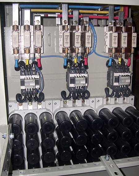
In centralized power factor correction automatic assemblies are normally used (see below automatic power factor correction) with banks divided into steps, installed directly in the main distribution boards. The use of a permanently connected bank is possible only if the absorption of reactive energy is quite constant all day long.
The centralized solution allows an optimization of the costs of the capacitor bank, but presents the disadvantage that the distribution lines on the load side of the power factor correction device shall be sized keeping into account the full reactive power absorbed by the loads.
4. Combined power factor correction
This solution derives from a compromise between the two solutions of distributed and centralized power factor correction and it exploits the advantages they offer.
Combined power factor correction is prevailingly used in installations where large equipment only are frequently used; in such circumstances their power factor is corrected individually, whereas the power factor of small equipment is corrected by the centralized modality.
5. Automatic power factor correction
In most installations there is not a constant absorption of reactive power for example due to working cycles for which machines with different electrical characteristics are used.

An automatic compensation system is formed by:
- Some sensors detecting current and voltage signals;
- An intelligent unit which compares the measured power factor with the desired one and operates the connection and disconnection of the capacitor banks with the necessary reactive power (power factor regulator);
- An electric power board comprising switching and protection devices;
- Some capacitor banks.

To supply a power as near as possible to the demanded one, the connection of the capacitors is implemented step by step with a control accuracy which will be the greater the more steps are foreseen and the smaller the difference is between them.
Reference // Power factor correction and harmonic filtering in electrical plants – ABB


Thanks to the tutorials.
What are Type 1 and Type 2 power factor correction units ? Where are they applied ? what is the suitable type power factor correction unit for office buildings?
Very useful and understandable explanation .thanks a lot
Good information! i am working in engineering industry where there is no consistency of load and due to this difficult to connect the required size of Capacitor even with APFC.Because theo switch corretly, we need grading of capacitor capacities, but economically, that is not feasible. WNow, we are thinking about, thyristorized KVAr compensators.comments please!!
Nice article.
Factories in Yemen operate 100% on private power installations, mostly diesel gensets. Its a bit hard to convince owners on the benefits of having automatic PF panels. I’m looking for good literature explaining the benefits in a simple manner – to convince non technical owners. Any tips ?
I want to subscribe for newsletters. Thanks
Thank a lot Mr.Edvard Csanyi