
Electric motors & power factor influence
A low power factor causes poor system efficiency. The total apparent power must be supplied by the electric utility. With a low power factor, or a high-kilovar component, additional generating losses occur throughout the system.
 Why Raise the Power Factor? The Basics You Should Know. (photo credit: .see-tech.com)
Figures 1 and 2 below illustrate the effect of the power factor on generator and transformer capacity.
When the power factor is improved by installing power capacitors or synchronous motors, several savings are made:
- A high power factor eliminates the utility penalty charge. This charge may be a separate charge for a low power factor or an adjustment to the kilowatt demand charge.
- A high power factor reduces the load on transformers and distribution equipment.
- A high power factor decreases the I2R losses in transformers, distribution cable, and other equipment, resulting in a direct saving of kilowatt-hour power consumption.
- A high power factor helps stabilize the system voltage.


So, how to improve power factor?
To improve the power factor for a given load, the reactive load component (kvar) must be reduced.
This can be accomplished by the use of a power capacitor, as illustrated in the power diagram in Figure 3, resulting in a net decrease in the angle θ or an increase in the power factor.

Several methods are used to improve the power factor in a system installation. One method that can be employed in large systems is to use synchronous motors to drive low-speed loads that require continuous operation.
The synchronous motor is adjusted to operate at a leading power factor and thus provide leading kilovars to offset the lagging kilovar of inductive-type loads such as induction motors.
Synchronous motors are usually designed to operate at an 80% leading power factor and to draw current that leads the line voltage rather than lags it, as is the case with induction motors and transformers.
For example, consider a load of 2000 kW at a 70% lagging power factor. The utilization of a 200-hp synchronous motor operating at an 80% leading power factor will increase the overall system power factor from 70% lagging to 85% lagging.
Using power capacitors
The more popular method of improving the power factor on low voltage distribution systems is to use power capacitors to supply the leading reactive power required.
The amount and location of the corrective capacitance must be determined from a survey of the distribution system and the source of the low-power factor loads.
In addition, the total initial cost and payback time of the capacitor installation must be considered.
The power factor capacitors are connected across the power lines in parallel with the low-power factor load. The number of kilovars of capacitors required depends on the power factor without correction and the desired corrected value of the power factor.
The power factor and kilovars without correction can be determined by measuring the power factor, line amperes, and line voltage at the point of correction.
For a three-phase system,
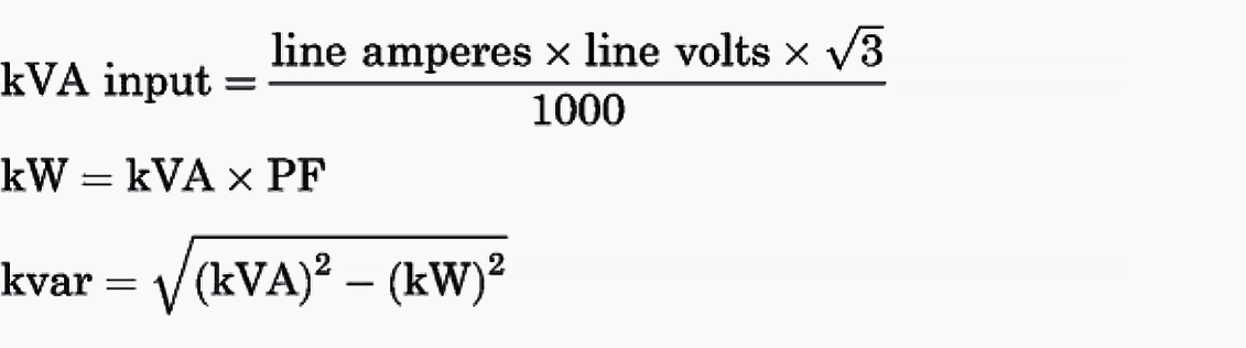
Or the line kilowatts, line amperes, and line voltage can be measured. Then,
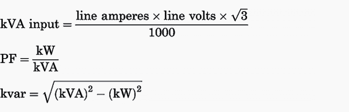
The capacitive kilovars required to raise the system to the desired power factor can be calculated as follows:
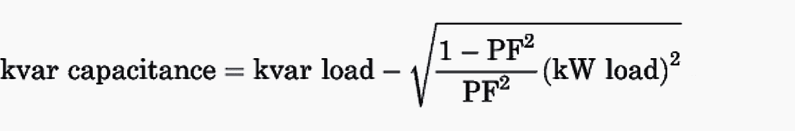
where PF is the desired power factor.
Let’s take an example…
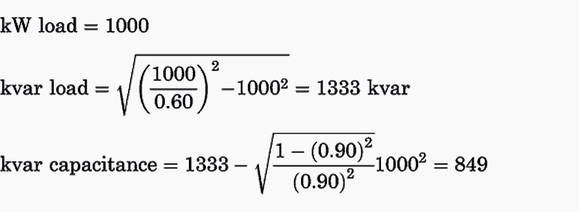
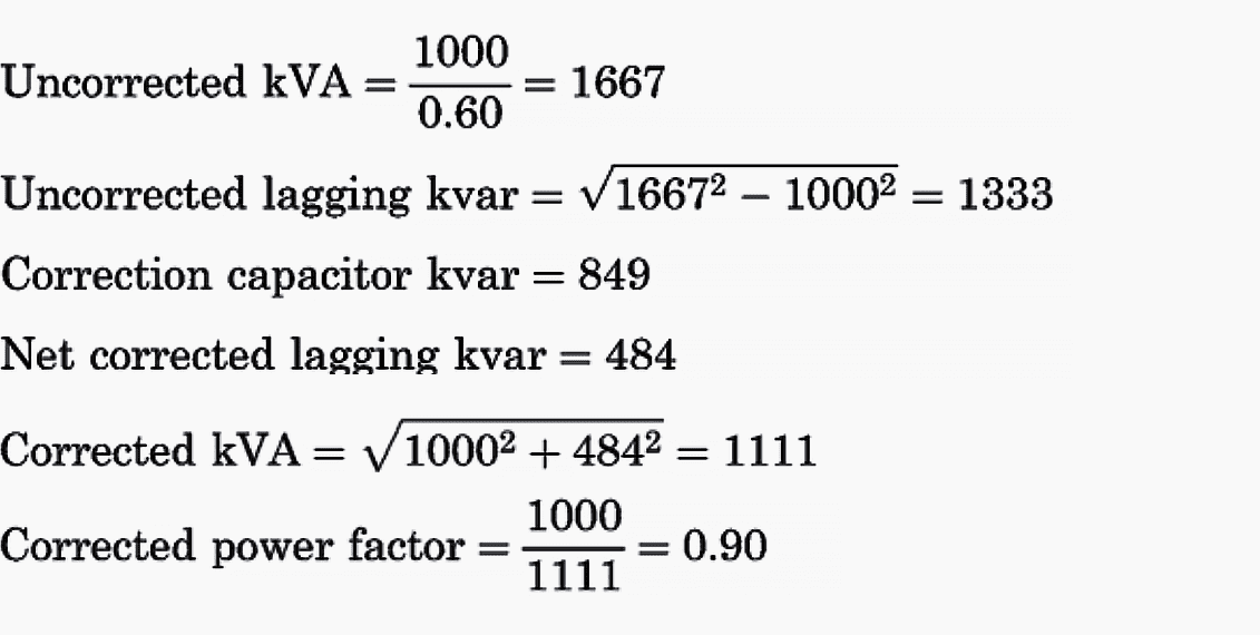
For example, consider a 1000-kW load with a 60% power factor, which one wishes to correct to 90%:
Tables such as Table 1 have been developed and are available from most power capacitor manufacturers to simplify this calculation. Table 1 provides a multiplier to be applied to the kilowatt load to determine the capacitive kilovars required to obtain the desired corrected power factor.
Consider the same 1000-kW load with a 60% power factor which one wishes to correct to 90%.
Table 1 – Power Factor Correction Factors
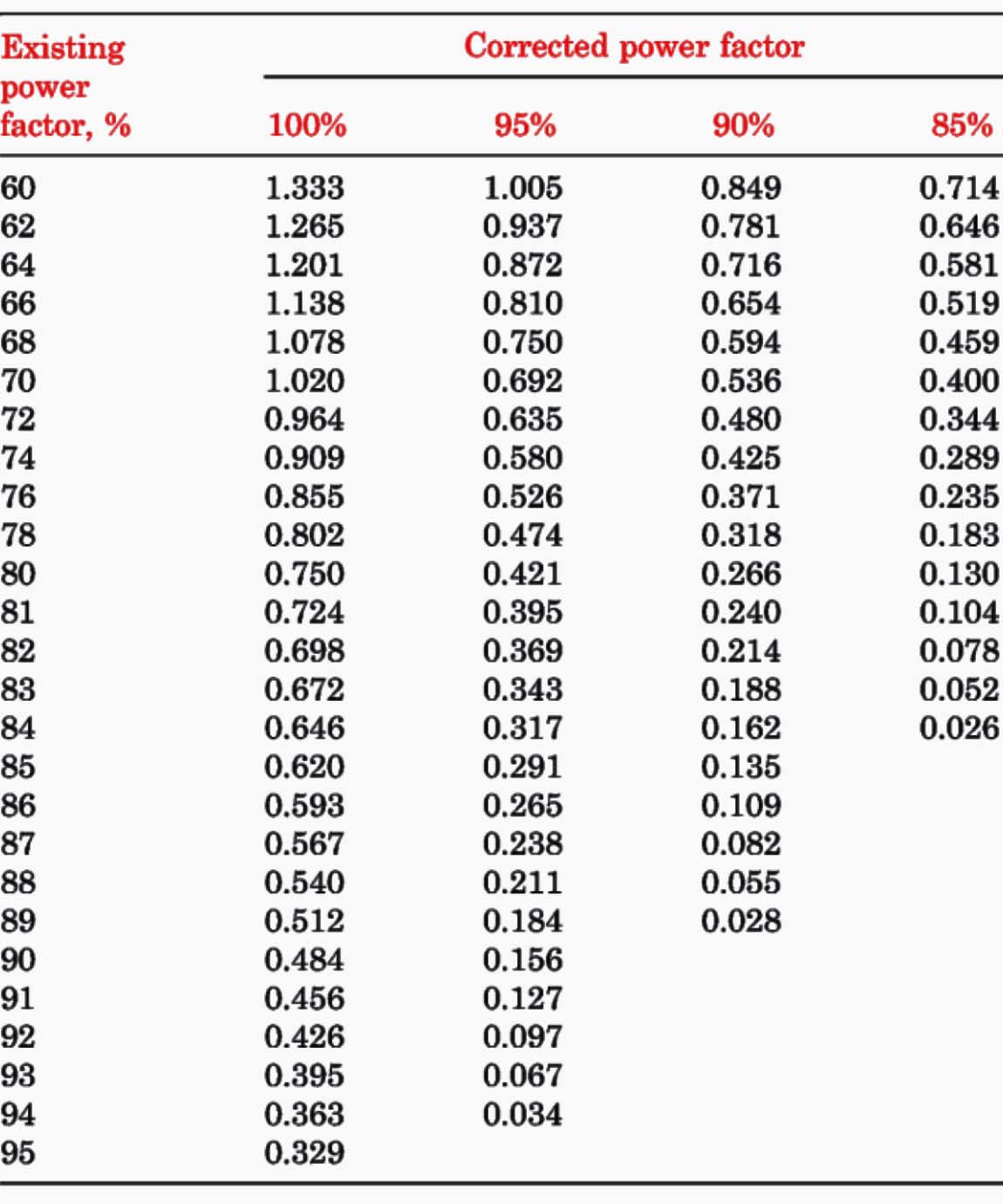
From Table 1, for the existing power factor (60%) and the corrected power factor (90%), the power factor correction factor is 0.849. Thus, the number of kilovars of capacitance required is 1000 × 0.849 = 849 kvar.
Let us verify this calculation:
Adding corrective kilovars
Over the years, there have been several guidelines used for the selection of induction motor power factor correction capacitors. Three of these guidelines are as follows:
- Add corrective kilovars of capacitors equal to 90% of the motor no-load kilovolt-amperes.
- Add corrective kilovars of capacitors equal to 100% of the motor no-load kilovolt-amperes.
- Add corrective kilovars of capacitors equal to 50% of the motor full-load kilovolt-amperes.
Table 2 is a comparison of these methods of selecting correction capacitors for some typical four-pole, 1800-rpm induction motors.
Table 2 – Comparison of Power Factor Correction Methods

The question is: What is a typical motor in regard to power factor?
Figure 4 shows the variation in full-load power factor for standard four-pole, 1800-rpm induction motors. Figure 4 is based on published data from 10 electric motor manufacturers.
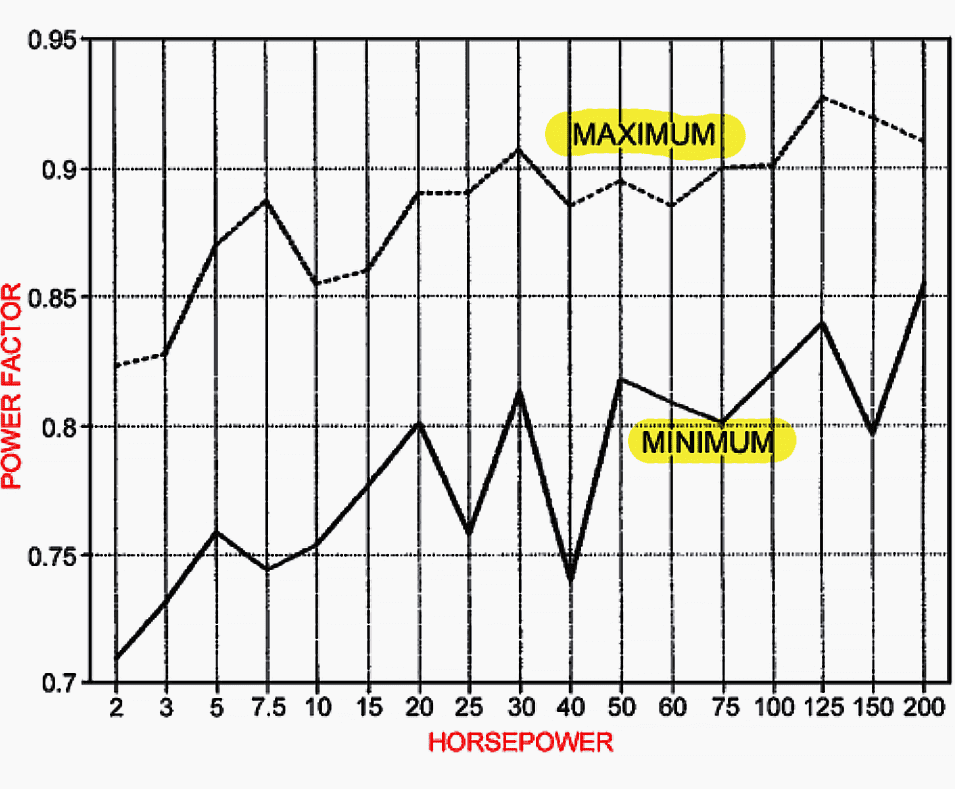
The difference in the full-load power factor for a specific horsepower rating can vary by 5 to 15 points. Therefore, it is best to know the power factor information on the specific motors requiring power factor correction.
The no-load methods of selecting correction capacitors are conservative and increase the corrected power factor to 95% or higher. However, the no-load information is not readily available. In contrast, the full-load power factor and efficiency are generally available either as published literature or on the motor nameplate.
These data can be used to calculate the motor power factor and input kilowatt-amperes.
Under partial-load conditions, the corrected power factor can be over 0.90 leading. The higher the horsepower of the motor, the more likely it is that the corrected power factor can be leading at partial loads.
A partial motor load is not an unusual condition.
Studies indicate that the average load on induction motors rated 125 hp and larger ranges from 50 to 85% of full-load rating. For 1800-rpm induction motors the power factor at 50% load is usually 0.07 to 0.14 points lower than the power factor at full load.
If the capacitor correction is not used to supply kilovars for other uncorrected motors on the same circuit, a value lower than 50% of the full-load input kilovolt-amperes should be used for the correction kilovars.
NEMA Recommendations
In the application of power factor correction capacitors at the motor location, NEMA recommends the following procedure based on the published or nameplate data for the electric motor:
Procedure #1
The approximately full-load power factor can be calculated from published or nameplate data as follows:

where:
- PF = per unit power factor at full load (per unit PF = percent PF/100)
- hp = rated horsepower
- E = rated voltage
- I = rated current
- Eff = per unit nominal full-load efficiency from published data or as marked on the motor nameplate (per unit Eff = percent Eff/100)
Procedure #2
For safety reasons, it is generally better to improve the power factor for multiple loads as a part of the plant distribution system.
In those cases in which local codes or other circumstances require improving the power factor of an individual motor, the kilovar rating of the improvement capacitor can be calculated as follows:
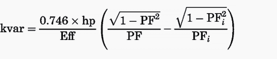
where
- kvar = rating of a three-phase power factor improvement capacitor
- PFi = improved per unit power factor for the motor-capacitor combination
Procedure #3
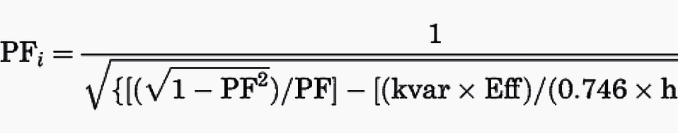
In some cases, it may be desirable to determine the resultant power factor PFi, where the power factor improvement capacitor selected within the maximum safe value specified by the motor manufacturer is known.
The resultant full-load power factor PFi can be calculated from the following:
The level to which the power factor should be improved depends on the economic payback in terms of the electric utility power factor penalty requirements and the system energy saved because of lower losses.
In addition, the characteristic of the motor load must be considered. If the motor load is a cyclical load that varies from the rated load to a light load, the value of corrective kilovar capacitance should not result in a leading power factor at light loads.
To avoid this possibility, NEMA recommends that the maximum value of the corrective kilovars added be less than the motor no-load kilovar requirement by approximately 10%.
Thus, Maximum capacitor kvar for three-phase motors:

where:
- INL = motor no-load line current
- V = motor line voltage
For example, consider a 50-hp, 1800-rpm induction motor operating on a 230-V, three-phase, 60-Hz power system.
Table 3 shows the performance of this motor at various loads without power factor correction. Table 4 shows the full-load performance with various values of correction capacitor kilovars, including 100% of the no-load kilovolt-amperes (13.7 kvar) and 50% of the full-load kilovolt-amperes (23.7 kvar).
Table 3 – Induction Motor Performance Without Power Factor Correction

Table 4 – Induction Motor and Capacitor Performance with Power Factor Correction at Full Load
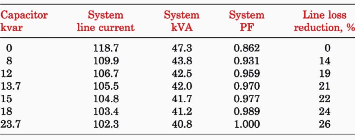
These values of kilovars correct the power factor to 0.97 and unity, respectively.
Based on 4000 hr/yr operation at 5¢/kWh for electric energy, a correction to unity power factor could result in a saving in energy costs of $70/yr. The combined motor–capacitor performance at partial loads is shown in Table 5.
Note that at partial loads with the higher values of corrective kilovars the power factor can be very leading.
Table 5 – Induction Motor and Capacitor Performance with Power Factor Correction at Various Loads
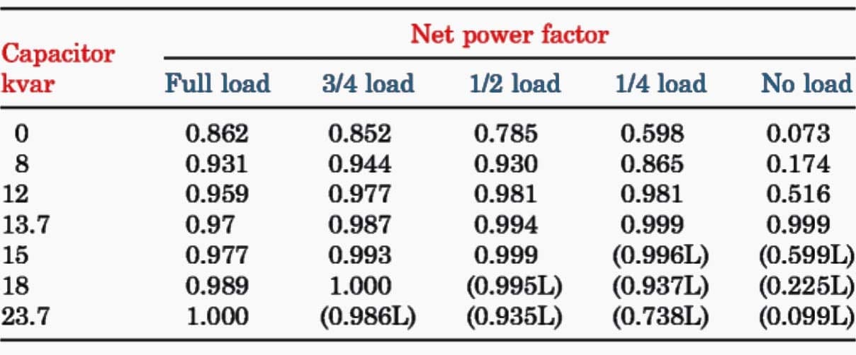
Figure 5 shows the comparison of the corrected and uncorrected power factor at various level of kilovar correction for the 50-hp induction motor.
WARNING! The high level of power factor correction should be avoided if the motor is going to be operating at partial loads and the capacitors are connected directly to the motor terminals.

The application of capacitor kilovars up to the no-load kilowatt-amperes results in a lagging power factor for all load conditions.
The National Electric Code (NEC) has removed any restrictions on the size of power factor correction capacitors applied to induction motor circuits. This places the responsibility on plant electrical engineers to select the power factor correction strategies that best suit their plant operations.
Reference // Energy Efficient electric motors by Marlin O. Thurston; Department of Electrical Engineering The Ohio State University Columbus, Ohio


Thanks for a comprehensive explanation.
Nice explanation and understanding
Explained power factor and its effect in most simplest way.
Nice presentation very informative. Power factor really a big help in power system specially in system where inductive loads are significant in numbers.
I would like to share my observations about the impact of solar power in-feed connection in power factor. Our system is 400V/230V, 60hz capacitor banks are already in place and most of the time, average pf will not fall below 95% both day and night operation.
There was this solar project that is connected in Low voltage side of the system. The solar energy setup would be: solar cell -> inverter -> inverter panel -> low voltage switch gear. My observation during daytime, power factor decreases from 95% to 20% depending on the harvest of solar power. Power factor will increase to 95% when solar energy is not there. Do you have any case study regarding this one?
Thank you
Solar Plant is capable of feeding reactive power in case load demands or in case of poor GRID power factor. Thus pooer power factor in case Solar Power Plant is on, is not possible. There may be some other reason for poor power factor.
Solar PV Plant is designed to provide power at 30 degree leading to 30 degree lagging depending upon requirement and Grid conditions at load end.
Clear and good explanation of pf issues
It really helps
Thanks for the wonderful and well articulated information on power factor collection.
Would you please write some comments about power factor when VSD is applied.
Please ex plane How to buildup harmonic(Voltage & Current) in LV system & how to reduce that harmonic(Current harmonic & Voltage Harmonic), Kindly request If you have basic cause material for that please send me, Thanks.
Concept clear of power factor
Thanks
Great piece of information well explained