
Estimated Study Time: 19 minutes
Substation automation functions
Substation automation involves the deployment of substation and feeder operating functions and applications ranging from SCADA and alarm processing, to integrated volt-var control in order to optimize the management of capital assets and enhance operation and maintenance efficiencies with minimal human intervention.
 Why to automate power substation? What do you get? - Application functions and applications of a substation automation and protection (on photo: 115kV control and protection panel)
It is evident that substation automation is implemented to reduce human intervention and to improve the operating efficiency of the system.
Distribution SCADA will have the basic functions like monitoring and control, report generation, and historical data storage and several functions for special application in the substation automation scheme.
The following sections will elaborate on the application functions.
- Integrated protection functions: Traditional approach and IED-based approach
- Automation functions:
- Enterprise-level application functions:
1. Integrated protection functions: Traditional approach and IED-based approach
In the traditional approach, the relays had hardwired inputs from the instrument transformers, and from the relays, hardwires carried the trip signals to the circuit breakers, as shown in Figure 1.
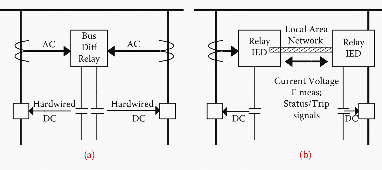
In the IED-based modern approach, the information from instrument transformers will reach the relay IEDs via LAN, the relays exchange information via LAN, and with the process bus becoming a reality, the circuit breakers will receive a trip signals via a generic object-oriented substation event (GOOSE) message traveling in the process bus, as illustrated in Figure 1b.
In case of a breaker failure, in the traditional protection wiring scheme, the hardwiring will carry the trip signal to the backup protection scheme, as shown in Figure 2a.
On the other hand, in a modern protection scheme, the backup protection is initiated via LAN as given in Figure 2b, which reduces the wiring tremendously and also will utilize alternate pathways.
Protection functions like automatic reclosing and bus differential schemes can be implemented, and breaker failure can be dealt with effectively.
The benefit lies in the fact that separate protection relays can be avoided, and thus performance improvement and reliability enhancement are achieved.
2. Automation functions
The substation automation application functions include intelligent bus failover, automatic load restoration, adaptive relaying, and equipment condition monitoring, which are explained in the following sections.
2.1 Intelligent bus failover and automatic load restoration
This scheme is generally used in a distribution substation where there are two transformers and a normally open bus tie breaker.
When a transformer in a substation fails, the simple bus failover scheme transfers the load to the healthy transformer in the substation, which may overload the healthy transformer and lead to another failure.
Hence, the bus failover schemes have been disabled in some cases.
The substation firm capacity is limited by the load (overload) that can be carried by the healthy transformer. However, in an intelligent bus failover scheme, the substation automation system will ensure that the healthy transformer is not overloaded.
This can be done by load shedding one or a few of the outgoing feeders temporarily. These feeders can be supplied from an adjacent substation by closing a tie switch, and the disruption in load can be minimized.
“Intelligent” load transfer will allow higher loading under normal conditions, as the substation firm capacity is limited to the amount of load that can be carried following a single contingency, like a transformer failure.
Figure 3 shows the fault on transformer B. Circuit breakers 1 and 2 will trip and isolate transformer B, and circuit breaker 3 will be closed to transfer the load on to transformer A, which will get overloaded and may have to shed load by opening circuit breaker 4.
However, the load can be transferred subsequently by connecting the line to the adjacent substation automatically by closing breaker 5.
2.2 Supply line sectionalizing
The distribution substations are often tapped off a supply line without high side breaker protection. This creates a problem, and considerable load may be out of service until the field crew arrives.
The benefit is that improvement in reliability as the service to substations that are without power can be restored as quickly as possible. The outage duration is reduced from 30 to 1 or 2 min.
How sectionalizers work?
Around 80% of the faults in the medium-voltage overhead lines are of transient nature and thus often self-clearing type. To restore the supply for the faulty feeder after line tripping, different autoreclosing schemes are employed.
In case the feeder is affected by a non-self-clearing type of fault, a lot of customers are affected by a long supply break after several unsuccessful autoreclosing attempts. If the actual fault is close to the end of the feeder, the customers closer to the substation could be still supplied if the faulty section of the feeder could be isolated.
For such cases, the optimally located automated sectionalizers can be the answer.
The automated sectionalizer counts the reclosing attempts made by the upstream device, like reclosing breaker at the upstream substation, and after a pre-selected number of attempts, it automatically opens during the de-energized period of the autoreclosing sequence.
Following diagram shows a simple radial feeder case of utilizing the functionality of an automated sectionalizer together with the circuit breaker’s autoreclosing scheme for discriminative fault isolation.

When the fault appears on the overhead line section beyond the sectionalizer, the protective relaying at the supplying substation and at the sectionalizer recognizes the case.
The protective relaying at the substation starts the autoreclosing sequence by tripping the circuit breaker in time of T1. The sectionalizer acknowledges this action. After a preset time delay (T2), the circuit breaker recloses. Since the fault has not been cleared, the circuit breaker trips again after a preset time delay of T3. The sectionalizer commences its opening cycle during the feeder’s de-energized period of T4.
The actual sectionalizer opening command is issued after a preset time delay of T5.
After the time delay of T4 of the autoreclosing scheme has elapsed, the sectionalizer is fully open and the circuit breaker recloses, energizing the healthy sections of the feeder.
2.3 Adaptive relaying
This is very important. Adaptive relaying is the process of automatically altering the settings of protective relay IEDs based on the system conditions.
This can be of much help to an operator when there is a crisis in the system, with main lines and generators tripping.
The special protection function of the substation automation system can play a role by altering the settings of some of the relay IEDs.
As an example, in the event of tripping of a critical generator, a line may get heavily loaded due to the diversion of power from other sources. Under normal circumstances, this will lead to the tripping of this line which may escalate to an emergency situation. The master at the control center will detect the trip and can inform the corresponding SA system of the event.
The SA system can switch the appropriate relays to the new settings to carry the required power until the crisis is over and then can switch back to the original settings.
2.4 Equipment condition monitoring (ECM)
Many electric utilities have employed ECM to maintain electric equipment in top operating condition while minimizing the number of interruptions.
This approach is applied most frequently to substation transformers and high-voltage electric supply circuit breakers to minimize the maintenance costs of these devices, by eliminating the time-based routine testing and thus saving significant labor and material cost.
The number of catastrophic failures is reduced by reducing the repair cost and avoiding forced outages. Dynamic equipment rating is feasible by which more capacity can be squeezed out of the existing equipment, thus improving the availability.
The life of the equipment is thus extended, and even a year or two extension can produce significant savings.
The ECM monitoring devices include:
- Dissolved gas in oil monitoring samples
- Moisture detectors
- Load tap changer monitors
- Partial discharge of acoustic monitors
- Bushing monitors
- Circuit break monitors (GIS and OCB)
- Battery monitors
- Expert system analyzers
ECM is an added advantage of substation automation.
3. Enterprise-level application functions
Once the substation is automated, there are many application functions that can be implemented at the enterprise level. The final level indicates the utility enterprise–related implementations in Table 1 below.
| Utility Enterprise | |
| Level III | Substation Automation functions |
| Level II | IED Integration |
| Level I | IED Implementation |
| Power system equipment (transformers, breakers, etc.) |
First there is the power system equipment such as transformers, circuit breakers, and intelligent instrument transformers and sensors. The first level is IED implementation where different IEDs are installed in the substation.
The second level is IED integration, utilizing the two-way communications of the IED. IEDs from different vendors and with different functionalities have to be integrated to form a cohesive protection, monitoring, and control system, which also performs a number of other functions like waveform recording and metering.
Last, there is the utility enterprise where the integration of different control centers can be performed and utility-wide data sharing and applications can be run.
3.1 Disturbance analysis
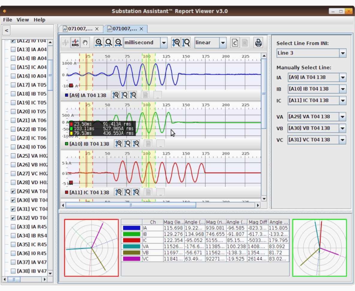
Disturbance analysis is an added advantage when IEDs are implemented, as they have inherent capabilities to record the fault waveform, and also the facility to time stamp the measured operational data.
These values can be used to recreate a disturbance sequence as the time stamping to the level of milliseconds or less will help the operator and other personnel in the utility to assess the situation and take corrective action for the next disturbance.
For example, in case of an islanding of a section of the power system, the faults, line tripping, overloading and underloading, and tripping of generators may happen in quick succession. After the islanding the utility personnel must assess the situation and determine the correct sequence of events.
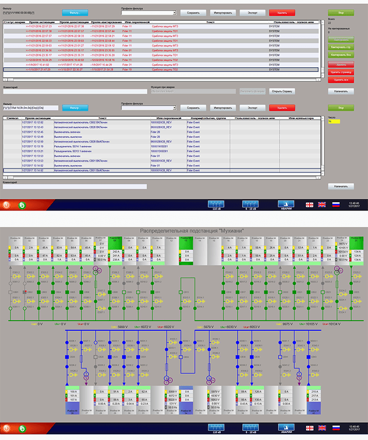
Visualization and user interface can be implemented as client-side application executing visualization application or user interface on client computers (Figure 6).
Direct notifications to users and reports customized and formatted for particular user groups should be done using all the available technology means. Additional “intelligence” may be incorporated into reports disseminated based on event priorities and user category.
3.2 Intelligent alarm processing
Intelligent alarm processing is of utmost importance in a control room to help the operator from getting confused by the battery of alarms triggered by an event.
3.3 Power quality monitoring
Power quality is an important factor in today’s power system operation scenario for two reasons. The quality of power deteriorates due to the influx of new power electronic devices which flood the system with harmonics and ripples.
But quality power is a must for many devices to operate optimally, and a large number of manufacturing facilities require quality power for precision manufacturing.
Necessary corrective action can be taken and the power quality can be maintained by the utility.
3.4 Real-time equipment monitoring
Real-time equipment monitoring is an offshoot of the equipment condition monitoring discussed earlier. Traditionally, power system equipment is loaded to the rated capacity under normal conditions, whereas if the equipment is condition monitored, the loading can be based on actual conditions, rather than on conservative assumptions.
The loadability can be derived, and it is reported that 5% to 10% additional loading can be achieved by this activity. Hence, the utility can squeeze more capacity out of the existing equipment and delay investment in new equipment.
References //
- Power System Scada and Smart Grids by Mini S. Thomas and John D. McDonald (Purchase hardcopy from Amazon)
- Distribution Automation Handbook by ABB
- Automated Fault and Disturbance Analysis: Understanding the Configuration Challenge by M. Kezunovic, Fellow, IEEE, S. Sternfeld, M. Datta-Barua, Member, IEEE, D. Maragal, Member, IEEE, and T. Popovic, Senior Member, IEEE
Related electrical guides & articles


Edvard Csanyi
Hi, I'm an electrical engineer, programmer and founder of EEP - Electrical Engineering Portal. I worked twelve years at Schneider Electric in the position of technical support for low- and medium-voltage projects and the design of busbar trunking systems.I'm highly specialized in the design of LV/MV switchgear and low-voltage, high-power busbar trunking (<6300A) in substations, commercial buildings and industry facilities. I'm also a professional in AutoCAD programming.
Profile: Edvard Csanyi

updated insight into and technical Information about, Optimizing HV and LV grid functionality, Distribution Automation, SCADA, Advanced Metering Systems for Network Optimization etc..