
Estimated Study Time: 29 minutes
Wiring low-voltage switchboard
To be clear from the very beginning of this article, there is no standard model for wiring low voltage switchboards and panelboards. However, for the wide variety of installations and ranges of power ratings, there are local work practices, regulations and of course international standards. There are numerous types of the conductor in the LV switchboard. The best choice depends on what they are to be used for, which is clearly defined for installations.
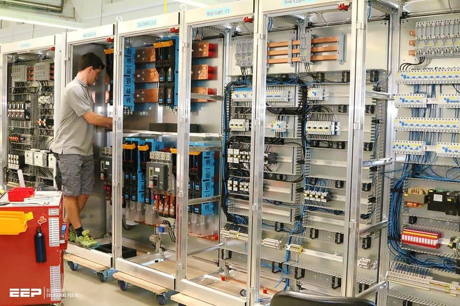 Dos, don’ts and precautions in wiring cables and conductors inside low-voltage switchboard (photo credit: schubert.tech)
However, this is not always the case for distribution switchboards. In addition to the current-carrying capacity, this choice is dependent on the requirements relating to the panel, the rated voltage, the installation method, the type of insulation, the types of application, etc.
I always like to see is the proper “wiring hygiene” when looking at the switchboard. If the wiring is done properly and clean, it will make much easier troubleshooting and maintenance in the future.
This technical article covers recommendations for choosing cross-sections of the wiring conductors inside switchboards, their connection methods, various wiring dos, don’ts and precautions in protecting from short-circuit and magnetic effect.
- Cross-sections of the wiring conductors inside switchboards
- Connecting conductors (recommendations)
- Wiring precautions
- Wiring upstream of protective devices
- Permanently energized wiring circuits
1. Cross-sections of the wiring conductors inside switchboards
The choice of conductors to be used inside the switchboard and their cross-sections are the responsibility of the original manufacturer. The conductors must have a minimum cross-section conforming to IEC 60364-5-52. Examples of how to adapt this standard for the conditions inside the switchboard are given in the following table which is taken from IEC 61439-1.
There are two types of conductor:
- PVC for conductors with PVC or rubber insulation, generally used for wiring conductors up to 35 mm²
- PR for conductors with polyethylene or elastomer insulation. In practice these are usually reserved for cross-sections greater than 35 mm²
The installation and ambient temperature conditions have been named empirically:
- IP < 30 for conductors installed with good cooling conditions (enclosure open or naturally ventilated, low to medium wiring density, enclosure internal temperature similar to the ambient temperature up to 35°c)
- IP > 30 for conductors installed in poor cooling conditions (sealed enclosure, high wiring density, multi-core cables, enclosure internal temperature that may reach 50°c)
Table 1 – Guide values for minimum cross-sections (in mm2)
Where:
- Imaxc – Current-carrying capacity I30 for a three-phase circuit from IEC 60364-5-52, table B.52.10, column 5 (installation method: point F in table b.52.1). Values for
cross-sections less than 25 mm2 calculated according to IEC 60364-5-52 Annex D. k2= 0.88 (point 4 in table B.52.17, two circuits) - Imaxd – Current-carrying capacity I30 for a three-phase circuit from IEC 60364-5-52, table B.52.10, column 7 (installation method: point G in table B.52.1). Values for cross-sections less than 25 mm2 calculated according to IEC 60364-5-52 Annex D. (k2= 1)
Column 1 applies when conductors from different circuits are installed touching one another and grouped together (for example, installation in trunking or in strands).
Figure 1 – Several circuits in the same trunking and all wiring in vertical and horizontal trunking: Column 1 installation
Column 2 applies when the conductors or cables are separated in the open air (see Figure 2 below).
Figure 2 – Conductors not touching, held in place with guide rings: Column 2 installation
Figure 3 – Horizontal circulation “in the open air”, only the vertical conductors are grouped in trunking: column 2 installation as here. If the packing ratio of the vertical trunking is high: column 1 installation
The usual cross-sections of protective conductors (PE) in switchboards are given below.
Table 2 – Cross-sections of protective conductors in switchboards according to the current
| I (A) | SPE (mm2) |
| 10 | 1.5 |
| 16 | 2.5 |
| 20 | 4 |
| 25 | 4 |
| 32 | 6 |
| 40 | 10 |
| 63 | 16 |
| 80 | 16 |
| 100 | 16 |
| 125 | 25 |
| 160 | 35 |
| 200 | 50 |
| 250 | 70 |
| 315 | 95 |
| 400 | 120 |
| 500 | 150 |
| 630 | 185 |
| 800 | 240 |
| 1000 | 185 or 2×150 |
| 1250 | 240 or 2×165 |
| 1600 | 240 or 2×240 |
| > 1600 | SPE/4 |
The cross‑sections of the conductors to be used for wiring inside switchboards are not covered in a single standard document.
Standard IEC 60364
Standard IEC 60364 recommends that the cross‑sections are determined according to installation methods 31 and 32. In fact, the method is difficult to apply as it requires, for the application of the correction factors, information that will only be known after the installation has been carried out:
- Parts which run vertically,
- Parts which run horizontally,
- Groups,
- Number of layers,
- Separate conductors or cables, as well as
- Knowledge of the ambient temperature in the enclosure, which is always difficult.
Standard IEC 61439-1
Standard IEC 61439-1 does not recommend cross‑sections but stipulates a “current range” for the temperature rise tests. The conductors taken into consideration have PVC insulation and the ambient temperature is not specified. These conditions do not therefore cover all applications.
2. Connecting conductors (recommendations)
2.1 Conductors with rigid copper core
This type of conductor, which is by far the most widely used in fixed installations, does not require any particular precautions since the terminal to which it is connected is sized for the required cross-section and current. The quality and durability of the connections are assured by the use of an appropriate tool and compliance with the recommended tightening torques.
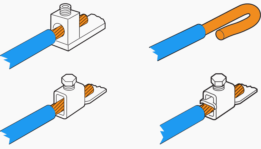
Connecting small conductors in direct pressure screw terminals requires some precautions to be taken:
- Do not tin the core where it is stripped as this could cause subsequent breaking of the conductor.
- Do not over-tighten, to limit shear.
- The end of the conductor can be folded back to provide better contact.
Figure 4 – Connecting conductors with rigid copper core
2.2 Conductors with flexible copper core
Due to the relative fragility of the strands which make up the core, connecting flexible conductors requires some precautions to be taken. Excessive tightening may shear the strands. an incorrect cross-section causes dispersion of the strands and poor contact.
Figure 5 – Connecting conductors with flexible copper core
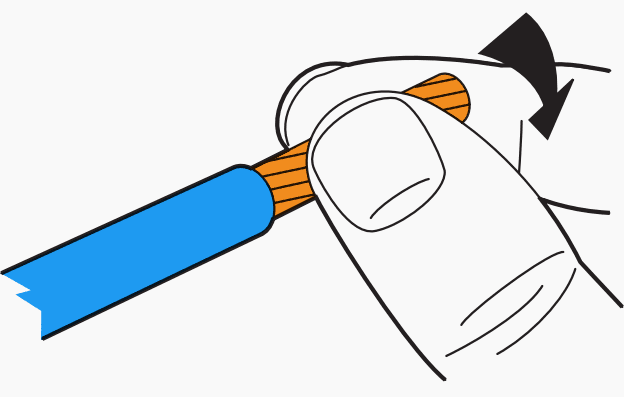
To avoid loosening and the risk of dispersion of the strands, it is recommended that the core is bent back on itself in the initial direction, often to the left.
Do not tin flexible conductors before connection: If tin is applied it may undergo a disintegration phenomenon over time known as “fretting corrosion”. The risk of dielectric breakdown makes the use of conductive contact grease inadvisable in damp or conductive atmospheres. It is preferable to fit cable ends, sleeves or lugs if the operating conditions are difficult.
The risks of shear and dispersion of the strands, especially inherent in direct screw terminals, can be avoided by using the crimping tool for ferrules.
2.3 Branching conductors
The simultaneous connection of two rigid conductors with the same cross-section is not generally possible upstream. That of two conductors with different types of core or cross-section is highly inadvisable. Downstream branching is possible. In this case the capacities, types of conductor and combinations are indicated on the products themselves or in their accompanying documentation.
2.4 PE conductors
Branching or connection in the same terminal is not permitted on protective circuits. Nor is it permitted on the terminals of operating devices (except for socket outlets, luminaires, lighting units, etc. as long as appropriate terminals are provided).
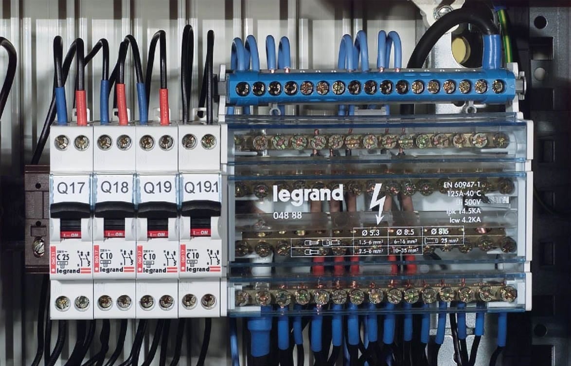
The branching required due to the large number of circuits must be carried out using appropriate, safe devices.
Figure 6 – Additional terminal block for neutral conductor on distribution block
2.5 Conductors with aluminium core
Aluminium is an excellent conductor and offers a favourable weight/conductance ratio for large cross-sections. Very widely used in power systems, its use is now being extended to include power distribution. A good understanding of the specific difficulties associated with connecting this metal is required in order to avoid subsequent problems which will certainly occur:
Problem #1 – In the open air aluminium quickly becomes coated with a thin, very hard insulating layer, alumina. It must therefore be connected immediately after stripping and if necessary after abrasive surface finishing.
Problem #2 – Aluminium expands a great deal more than other commonly used metals (iron, copper, brass, etc.) and this leads to inevitable loosening of the connections. The connection terminals for aluminium must therefore also be made of aluminium or an alloy, or have elastic devices (washers, strips) to compensate for these expansion differences.
Problem #3 – Aluminium has a very negative electrochemical potential (- 1.67 v) and will therefore tend to corrode when it comes into contact with many other metals. This “sacrificial anode” behaviour increases in damp or conductive environments. It is essential to avoid direct contact between aluminium and stainless steel, silver or copper.
When the metals used are chosen correctly and the atmosphere is dry, the risk of electrolytic corrosion is low. This risk increases in damp environments (water acts as an electrolyte in the battery that is formed). The use of a neutral grease (generally silicone‑based) limits this phenomenon.
Figure 7 – Using a neutral grease to limit the electrolytic corrosion
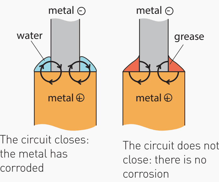
Table 3 – Equivalent cross-sections of aluminium/copper conductors
| Copper cross-section (mm2) | Aluminium cross-section (mm2) | |
| At same temperature rise | At same voltage drop | |
| 6 | 10 | 10 |
| 10 | 16 | 16 |
| 16 | 25 | 25 |
| 25 | 35 | 35 |
| 35 | 50 | 50 |
| 50 | 70 | 70 |
| 70 | 95 | 95 |
| 95 | 150 | 150 |
| 120 | 185 | 185 |
| 150 | 240 | 240 |
| 185 | 300 | 400 |
3. Wiring precautions
The wiring components must not suffer any damage due to mechanical or thermal forces. This damage can be caused by:
- Electrodynamic effects caused by short-circuits
- Expansions and contractions caused by temperature rises
- Magnetic effects caused by the current flowing through them
- Movement of the moving parts of the switchboard, etc.
It is also important to ensure compliance with the following points:
- Avoid the cables coming into contact with sharp edges and the moving parts of the switchboard
- Comply with the bend radius of the cables (values provided by the cable manufacturers)
- Check that the cables are not subjected to any pulling or twisting
- Check that the connections of the devices mounted on removable parts of the switchboard (doors, pivoting faceplates, etc.) are made using flexible cables and that these conductors are held in place by attachments other than the electrical connections.
3.1 Protection against the effects of short-circuits
Two destructive effects can affect conductors if there is a short-circuit:
- Thermal stress, against which protection is normally provided by the protective devices (fuses, circuit breakers)
- Electrodynamic stresses, including forces between conductors
When there is a short-circuit between two live conductors (most probable situation), the conductors through which the short-circuit current passes will tend to repel each other with a force that is proportional to the square of the current.
Multicore cables are designed to withstand the forces that may be exerted between conductors. However, the use of single-core cables requires particular precautions to be taken.
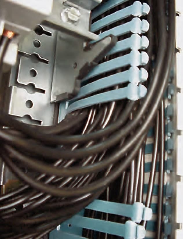
The information provided in the table below, intended to draw attention to the importance of attaching conductors correctly, does not on its own guarantee withstand to short-circuit conditions, which can only be simulated by tests.
Table 4 – Wiring precautions
| Prospective short circuit value (Ik) | Attachment of conductors | |
| Ik < 10 kA | No specific precautions (standard IEC 61439-1 does not stipulate any tests). | – |
| 10 kA < Ik < 25 kA | The conductors must be attached using clamps. they can be grouped together in stranded cables for the same circuit. |  |
| 25 kA < Ik < 35 kA | Conductors in the same circuit must be kept separate and attached individually. If they are grouped together in stranded cables, the number of clamps must be increased (one every 50 mm). |  |
| 35 kA < Ik < 50 kA | Conductors in the same circuit must be attached individually on a rigid support (crosspiece, profile) with no sharp edges. They must be physically separated. each attachment must consist of two crossed clamps. |  |
| Ik > 50 kA | At these short-circuit values, the forces become such that the attachment devices must be specially designed: for example, machined crosspieces and threaded rods. Stainless steel profiles and flanges can be used in some extreme cases. |  |
While the installation conditions of busbars are systematically precisely determined with regard to short‑circuits (distances between supports), this is not generally the case for the conductors inside switchboard panels. They are often the source of damage, and this risk should be clearly taken into account.
3.2 Protection against magnetic effects
High currents passing though conductors cause magnetic effects in the surrounding metal conductive parts. these effects can cause an unacceptable temperature rise of the materials. It is therefore essential to take some wiring precautions. “Hysteresis” loss associated with the saturation of the magnetic materials occurs in the frames created by the structural components (enclosure structures, chassis, support frames) located around the conductors.
As the vectorial sum of the currents is zero, that of the fields created is also zero.
Figure 8 – All the live conductors in the same circuit (phases and neutral) in the same metal (steel) frames
When it is not possible for all the conductors in the same circuit to pass through together without the insertion of ferromagnetic components (this could be the case with device supports, cable entry plates, dividers), they must be placed in supports made of non-magnetic material (aluminium, copper, stainless steel or plastic). This is recommended from 400 a per conductor upwards, and is essential above 630 A.
As far as possible, conductors should be in a trefoil arrangement to reduce the induced fields.
It is also possible to break the magnetic frame by removing components. In all cases, check that the mechanical strength of the support remains acceptable.
Figure 9 – It is advisable to remove the parts which create frames around a conductor
4. Wiring upstream of protective devices
Upstream of overcurrent protection devices (TN and IT neutral earthing systems) or residual current devices (TT system), protection against the consequences of a possible fault (between phases and metal conductive part) is not assured.
It is essential to avoid the risk of indirect contact using another means: In practice, the only measure that can be used to compensate for this is double insulation. This can be obtained directly using devices or by supplementary insulation on the installation.
The implementation of Class II upstream of the protective devices is based on four basic rules:
Rule #1 – The use of conductors or cables which have double insulation as a result of their composition.
Rule #2 – The provision of supplementary insulation around conductors that do not have this double insulation (installation in insulated ducting, insulated conduits or insulated enclosures).
Rule #3 – The use of insulating components which hold the bare conductive components in place (busbars) with an clearance double the conventional value.
Rule #4 – Clamping the conductors so that there can be no contact with a nearby exposed conductive part if they accidentally become detached or disconnected.
4.1 Location of conductive components in relation to the metal conductive parts
Example of 500 V insulation voltage
Figure 10 – Location of conductive components in relation to the metal conductive parts
These provisions assume that the minimum distances are permanently maintained, including when there are faults (electrodynamic forces), using appropriate clamping. The clearances can be replaced by thinner insulating components (screens, supports, separators), which have sufficient mechanical strength and a minimum dielectric strength of 2500 v or 4000 v.
Table 5 – Selection of conductors and installation requirements (IEC 61439-1)
| Type of conductor | Requirements |
| Bare conductors or single-core conductors with basic insulation, for example, cables conforming to IEC 60227-3 | Mutual contact or contact with conductive parts must be avoided, for example by using separators |
| Single-core conductors with basic insulation and a maximum permitted usage temperature of at least 90°C, for example, cables conforming to IEC 60245-3, or thermoplastic cables with PVC insulation, with heat-resistance conforming to IEC 60227-3 | Mutual contact or contact with conductive parts is permitted if no external pressure is applied. Contact with sharp edges must be avoided. These conductors must be loaded such that the operating temperature is no greater than 80% of the maximum permitted temperature for the use of the conductor |
| Conductors with basic insulation, for example cables conforming to IEC 60227-3, with supplementary secondary insulation, for example, cables covered individually with retractable sleeves or laid individually in plastic conduits | No additional requirements |
| Conductors insulated using a material with very high mechanical strength, for example, ethylene tetrafluoroethylene (ETFE) insulation, or conductors with double insulation with reinforced external sheath for use up to 3 kV, for example cables conforming to IEC 60502 | |
| Single-core or multicore cables in sheaths, for example cables conforming to IEC 60245-4 or to IEC 60227-4 |
Flexible bars have an insulation voltage of 1000 v. They can be classed as double insulation conductors by limiting the operating voltage to U0: 500 V (the insulation is then considered to be reinforced insulation) or, preferably, by holding the insulation of the bars in place mechanically (clamping, supports, their own rigidity) at an adequate distance from the metal parts (10 mm).
Table 6 – Cables considered as being double insulation
| Type of conductor | Requirements |
| U0: 500 V | U0: 250 V |
| U-1000 R12N | H05 RN-F |
| U-1000 R2V | H05 RR-F |
| U-1000 RVFV ** | H05 VV-F |
| H07 RN-F | H05 VVH2-F |
| A07 RN-F | FR-N05 VV5-F |
| FR-N1 X1 X2 | A05 VVH2-F ** |
| FR-N1 X1 G1 | |
| H07 VVH2-F |
** according to conditions of use.
5. Permanently energized wiring circuits
Some measurement, signalling or detection circuits have to be connected upstream of the switchboard’s main protective device. In addition to their protection against indirect contact, special precautions must be taken with these circuits:
Precaution #1 – Against the risks of short-circuits
Precaution #2 – Against the risks associated with the fact they that remain energized after breaking of the main protective device the double insulation specification must be applied to limit the risk of contact with the exposed conductive parts and measures must be taken so that any risk of short-circuit is unlikely.
The conductors of these unprotected circuits must be connected as securely as possible. The mechanical strength of the conductors must be taken into consideration when creating unprotected circuits:
- Conductors with single insulation (H07 V-U/R or H07 V-K) must be protected using an additional sheath or laid in ducting if there are risks of contact with parts which may cause injury,
- Conductors with a high degree of mechanical strength (with PTFE insulation) can be used directly,
- Single-core and multicore cables can be used without any additional sheath unless there are risks of hazards such as the presence of sharp edges.
The protective devices for permanent circuits must, of course, be chosen according to the current of the circuit to be protected and also the prospective short-circuit current at the supply end of the switchboard. Very high values often lead to the use of cartridge fuse type circuit breakers.
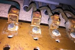
Figure 11 – Example of connection to separate copper plate on the connection. the screws have washers to prevent loosening
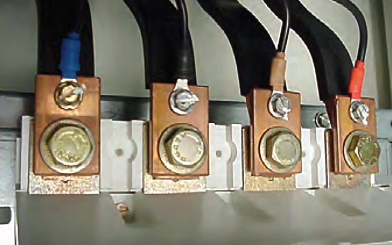
Do not rules
- Connect to the heads of screws: drilling the thread can weaken even the largest diameter screw!
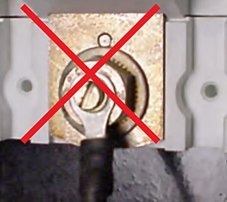
- Connect the wires between the lugs and the connection plate on the device: the wire may be cut and the area of the surfaces is compromised!
- Connect the large cross-section power supply cable directly in the terminals on the device: the hold is uncertain!
Figure 12 – Connecting the large cross-section power supply cable directly in the terminals on the device is forbidden
Warnings!
Permanently energized unprotected circuits have no specific marking (IEC 60364). It is however advisable to identify them clearly using the following type of wording:
“Caution, permanent circuits not broken by the main device”, with possible additional identification of the circuits concerned (for example: “voltage present”, “enclosure lighting”, “group detection”, etc.).
Standard IEC 60204‑1 (safety of machinery) recommends that these circuits are physically separated from the other circuits and/or identified by orange insulation on the conductors.
Source: Legrand
Related electrical guides & articles


Edvard Csanyi
Hi, I'm an electrical engineer, programmer and founder of EEP - Electrical Engineering Portal. I worked twelve years at Schneider Electric in the position of technical support for low- and medium-voltage projects and the design of busbar trunking systems.I'm highly specialized in the design of LV/MV switchgear and low-voltage, high-power busbar trunking (<6300A) in substations, commercial buildings and industry facilities. I'm also a professional in AutoCAD programming.
Profile: Edvard Csanyi

Your Engineering input is always inspiring. Please keep it up
Great article , 👏
This is great work that even inspires young graduates joining the industry. Keep it up
Very useful things are found in the article.
Many congratulations Edvard, as usual is a great article, thanks for all the knowledge shared.
such a good article. i hope i can read another article more.