Circuit diagram of PF relay
In order to measure electrical power the relay needs to receive the line voltage and current from a current transformer (CT) installed close to the metering point, if possible. To measure reactive power at the power factor relay especially, it must be ensured that the vectors of voltage and current are shifted by 90°.
In three-phase systems this is simple to realize by measuring the current in phase L1 and the voltage path is taken from the other two phases L2 and L3. The so-called current path of the power factor relays is standardized to either 5 A (mainly) or 1 A.
One has to take into consideration that the ratio of the current transformer is adapted to the load expected and the primary current will be transformed to the secondary side proportionally.
Figure 1 illustrates a simplified circuit diagram of how to wire the current path to the terminals k and l of the power factor relay.
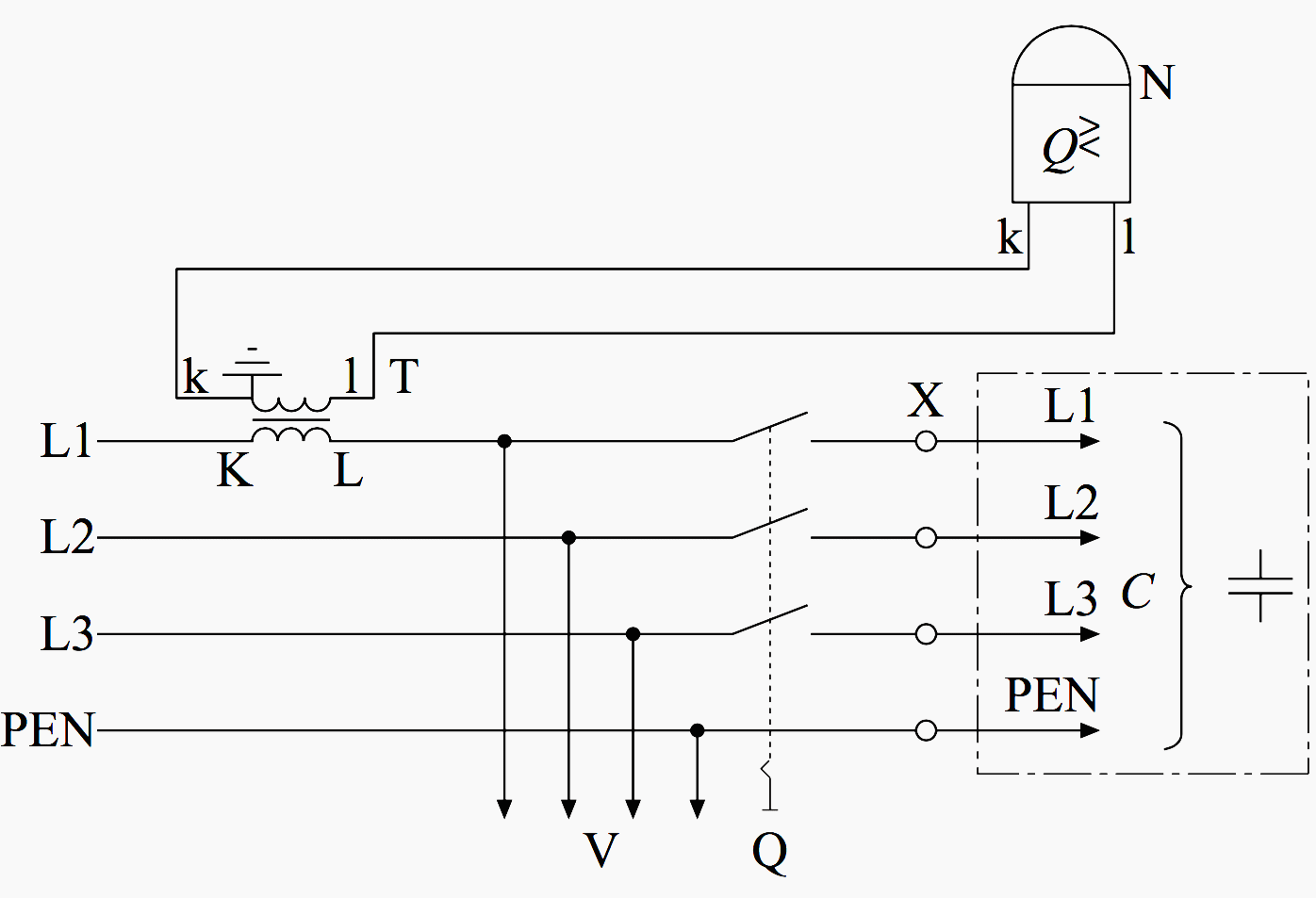

Where:
- V – loads (consumers)
- T – current transformer (CT)
- C – compensation (capacitor) bank
- Q – circuit breaker
- N – power factor relay
- K – terminals
In general the reactive power of a three-phase system is measured by means of the current transformer in one phase only chosen as desired, mainly L1 (or A).
According to Figure 2, there is the possibility of measuring the load either on the LV or on the MV side.
Alternatively, there is the method of mixed LV/MV measurement which is rarely used. In this method, voltage path for the power factor relay is taken from the LV side. However, the current path is taken from a current transformer installed at the MV side.
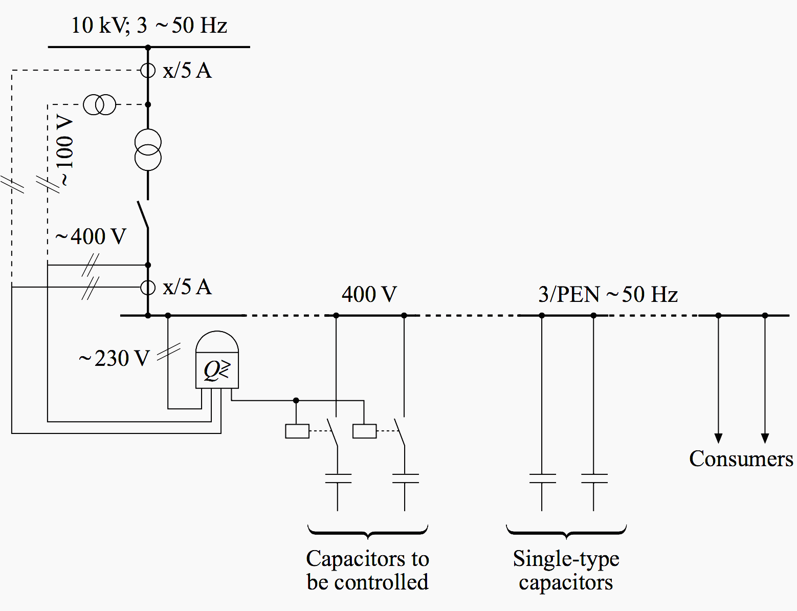

Although the mixed measurement is rarely in use, it is very important to discuss. It refers mainly to large industrial plants like car factories or steelworks. This method is considered if a voltage transformer on the MV side is not available. Incidentally, voltage transformers for metering purposes are not allowed to be used.
The method has the advantage that all consumers downside (L-side) from the current transformer are to be compensated, including the power transformer(s), by the compensation bank at the LV side.
Most applications use the LV method, because a separate current transformer on the MV side is not available all of the time, not to mention the costs.
It is a matter of course that the power transformers are not compensated by the automatic compensation bank on the LV side. Recall that the desired power factor cosφ, preset at the relay, is to be achieved at the location of the current transformer exclusively and consumers will be compensated only just downside (the L side of the current transformer), referring to the flow of energy.
Power Factor Correction Capacitors
Reference // Reactive power compensation by W. Hofmann






You can series connection in apfc controller of CT connection.
If your MSB and energy meter is far away. Then there will be a drop in powerfactor at energy meter. To overcome the issue you have to provide a capacitor at your msb panel -on direct.
Dear sir
How much % of capacitor (kvar) will connected against our transformer rating and our plant load indivisually.
This Electrical engineering portal is very nice for better understanding of the Electrical concepts So here my friends having number of problems arises in the power factor concepts & I am deeply concerned with this p.f concepts .Just we know that there are two types of loads inductive & capacitive. Meanwhile capacitive gives the leading p.f & inductive gives the lagging p.f. First of all check what kind of load are you consuming?? What kind of relay are you using?? Is it single or double or three phases??Is it 1CT or 3CT relay??? Out of these which Relay as well as the Capacitor are you using are of better quality??? The CT should be placed in the correct phase as well?? What kind of programming is done for the inputs of the capacitor bank?? Manual or auto sensing relays are also used for the p.f.Correct programming should be done as well as location of the CT with correct ratio is most important for the power factor correction. Most of most important is the voltage for the achievement of the unity power factor.
Thanks
Puneet Chouhan
Electrical Engineer & Consultant
Please make sure system harmonics level (THDi) is low.Utility energy meter read true power factor (=displacement pf x distrotion pf).But capasitor bank pf controller measure only displacement pf.Thats why two reading.
Hi
How can I connect two apfc panel with one current transformer..
I installed a APFC Panel. There is one issue is there that power factor reading in the controller and EB energy meter both are not matching. Please guide what could be the reason. I fixed CT in R phase in consumer load side and not in APFC panel input cable.
Dear all lecturer have.
methods and diagram very good if you attach a lecturer is very very good and easy.
Hi
how can i correct automatic closing up and down
-the sampling current between 0.9 — 2 amp
-the load current is between 200 amp –600 amp
-CT 800/5 A
– the capacitor banks rated 2*10 + 5*30 + 4*50 KVR units installed in parallel
-set up is don as usual
The problem is always the units are fully closed no increment or decrements seen
what should be the possible cusses
thank you
what is te genral percentage increase in watt consumption on adding capacitors so that pf rises from .90 to 1
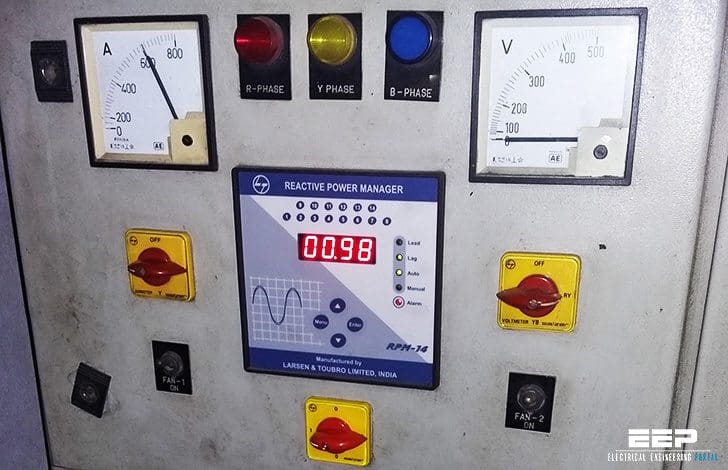
what company relay was that
Very básica.