
Estimated Study Time: 6 minutes
When Three Phase Faults Occur…
In a three phase power system, the type of faults that can occur are classified by the combination of conductors or buses that are faulted together. In addition, faults may be classified as either bolted faults or faults that occur through some impedance such as an arc. Each of the basic types of faults will be described and shown in Figure 1.
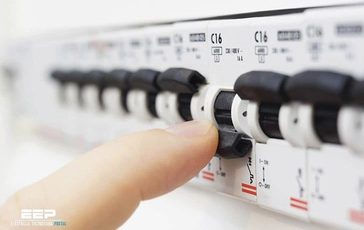 What Would Be The Worst Type Of Three Phase Faults And Why It Happens (photo credit: everreadyelectric.com)
It must be noted that in a majority of cases, the fault current calculation required for the selection of interrupting and withstand current capabilities of equipment is the three phase bolted fault with zero impedance.
Let’s go through each of the four three phase faults //
- Three phase bolted faults
- Bolted line-to-line faults
- Line-to-line-to-ground faults
- Line-to-ground faults

1. Three Phase Bolted Faults
A three phase bolted fault describes the condition where the three conductors are physically held together with zero impedance between them, just as if they were bolted together. For a balanced symmetrical system, the fault current magnitude is balanced equally within the three phases.
While this type of fault does not occur frequently, its results are used for protective device selection, because this fault type generally yields the maximum short-circuit current values.
Figure 1(a) provides a graphical representation of a bolted three phase fault.

Go back to three phase faults ↑
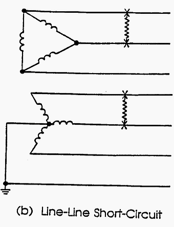
2. Bolted Line-To-Line Faults
Bolted line-to-line faults, Figure 1(b), are more common than three phase faults and have fault currents that are approximately 87% of the three phase bolted fault current.
This type of fault is not balanced within the three phases and its fault current is seldom calculated for equipment ratings because it does not provide the maximum fault current magnitude. The line-to-line current can be calculated by multiplying the three phase value by 0.866, when the impedance Z1 = Z2.
Special symmetrical component calculating techniques are not required for this condition.
Go back to three phase faults ↑
3. Line-To-Line-To-Ground Faults
Line-to-line-to-ground faults, Figure 1(c), are typically line-to-ground faults that have escalated to include a second phase conductor. This is an unbalanced fault. The magnitudes of double line-to-ground fault currents are usually greater than those of line-to-line faults, but are less than those of three phase faults.
Calculation of double line-to-ground fault currents requires the use of symmetrical components analysis. The impedance of the ground return path will affect the result, and should be obtained if possible.

Go back to three phase faults ↑
4. Line-To-Ground Faults
Line-to-ground faults, Figure 1(d), are the most common type of faults and are usually the least disturbing to the system. The current in the faulted phase can range from near zero to a value slightly greater than the bolted three phase fault current.
Calculation of the exact line-to-ground fault current magnitudes requires the special calculating techniques of symmetrical components.

However, close approximations can be made knowing the method of system grounding used. On ungrounded distribution systems, the line-to-ground fault currents are near zero.
Line-to-ground fault current magnitudes in distribution systems with a solidly grounded system will be approximately equal to the three phase fault current magnitudes. Determining line-to-ground fault currents on long cable runs or transmission lines will require detailed ground return path impedance data and detailed calculation techniques.
Go back to three phase faults ↑
Reference // IEEE Recommended Practice for Calculating Short-Circuit Currents in Industrial and Commercial Power Systems
Related electrical guides & articles


Edvard Csanyi
Hi, I'm an electrical engineer, programmer and founder of EEP - Electrical Engineering Portal. I worked twelve years at Schneider Electric in the position of technical support for low- and medium-voltage projects and the design of busbar trunking systems.I'm highly specialized in the design of LV/MV switchgear and low-voltage, high-power busbar trunking (<6300A) in substations, commercial buildings and industry facilities. I'm also a professional in AutoCAD programming.
Profile: Edvard Csanyi

Hi Edvard;
We love your articles over here at OneStep Power, you are a go-to reference for us. We do have a question though: You state “Line-to-ground faults, Figure 1(d), are the most common type of faults and are usually the least disturbing to the system.”
Our industry experience also agrees with you, however you do not cite evidence or an academic paper to support this claim. Do you have a reference we could review for further support of this statement? Thanks!!
Thank you Sarah. This statement is covered by IEEE Std. 551-2006 (Recommended practice for calculating short-circuit currents in industrial and commercial power systems).
What is the Fault Current of 33 KV DIstribution Line at a point??
Conductor #477 MCM
Please help me to Find the Result.
Dear Sir
We are the leading regional daily news paper publisher in INDIA. We have 2000KVA, 33KV/415Volts step down transformer with 2666amps. Three days back arround 2.00am at the time of 2200amps load, we faced very serious problem..i.e. we hard sounds from Aluminium bus duct with fire and smoke. Also same time transformer safety valves was blown and oil was came out (observed transformer winding temperature was raised to 100degress) my ACB was tripped and no effect to my equipment. After some time we notice above phenomina was occured after 15foot of tranformer secondry side bus duct and before 20foot of my ACB. Total bus duct length is 50foot.
Also noticed that, Transformer secondry side Neutral flexible link was cutted and touched with bus duct body.
What is the reason …1. due to Neutral was cutted & shorted with body or
2. Any short circuit in bus duct..(all coupling link bolt & nuts are in tight condition.
Please give your valuable suggestions in the above…
Hi,
Your information has certainly helped my electrical learning curve.
I’m a Mech. Engineer assessing damages and justifying reimbursement from FEMA for NYC due to Sandy Flooding. Electrical equipment was damaged via faults, but FEMA advised the equipment is above the flood level. What I have tried to explain is that the Submersible Sewage Pumps were compromised when the flood level inundated the splice boxes causing a 3 Phase Fault upon start-up with trailered portable generators. FEMA says there should have been protective devices between the Pump Motors and MCC, which would cause an open. I believe the overcurrent fused these devices as the design and conditions study did not protect for the max fault as it was the least likely to occur. Arc-flash study may have recommended that protective devices protect lower voltage/amperage equipment more prevalent to damage occurrences.
1. Am I correct and can other components be damaged during a 3 Phase fault past the protective device, and if so;
2. Can you assist in the proper language (Electrical Engineering) to explain and justify that it could happen?
Much appreciated,
Lenny Curcio