CB tripping time reduction
This function significantly reduces the tripping time of the circuit breakers closest to the source. It can be used for zone selective interlocking (ZSI) in closed ring networks. It applies to the phase overcurrent 50/51, directional phase overcurrent 67, ground fault 50N/51N and directional ground fault 67N protection functions, definite time and IDMT.

Protection relay logic usually includes two logic groups. Each group includes:
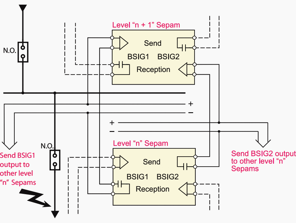
- Logic thresholds: protection units that send blocking signals (BSIG) and may be prevented from tripping by the reception of blocking signals.
- Time-based thresholds: protection units that may not be prevented from tripping by blocking signals and do not send blocking signals. They are used as backup for the logic thresholds.
When a fault occurs:
- The logic thresholds detecting the fault send blocking signals upstream
- The logic thresholds detecting the fault send a tripping command if they are not blocked by blocking signals
- The time-based (backup) thresholds detecting the fault send a tripping command
The first logic group is active if one of the following two conditions is met:
- Blocking reception 1 is assigned to a logic input Ixxx, except for motors which do not have this input.
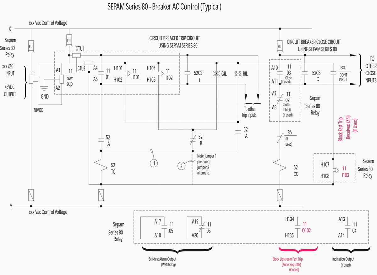
- Blocking send 1 is assigned to an output Oxxx. (O102 by default for SEPAM relay).


When the second logic group is present in the application, it is active under one of the following two conditions:
- Blocking reception 2 is assigned to a logic input Ixxx
- Blocking send 2 is assigned to an output Oxxx (O103 by default).
Relay software (in this case Schneider Electric’s software for SEPAM relays serie) usually indicates the type of threshold, logic or time-based, according to the input/output parameter setting.


In case of SEPAM relay, assigning protection devices to the two zone selective interlocking (ZSI) groups is fixed and cannot be modified. When ZSI is used, it is important to ensure that the measurement origin and logic group to which the unit is assigned are in accordance.
By default, the same logic group has the same measurement origin. When several origins are possible, the main channels Ia, Ib, Ic and Ir are assigned by default to the first group and the additional channels I’a, I’b, I’c, I’r to the second.
The duration of blocking signals lasts as long as it takes to clear the fault. If protection relay issues a tripping command, the blocking signals are interrupted after a time delay that takes into account the breaking device operating time and the protection unit reset time.
This system guarantees safety in downgraded operating situations (faulty wiring or switchgear).


Pilot Wire Test
Use the output relay test function in the protection relay software (for SEPAM – software SFT2841) to test the pilot wires that carry interlocks between breaker/relay functions.
Examples
1. Radial distribution with use of time-based discrimination
(T: protection setting time. As an approximation for definite time curves, this is assumed to be equal to the protection tripping time).


The upstream protection units are typically delayed by 0.3 s to give the downstream protection units time to trip. When there are many levels of discrimination, the fault clearing time at the source is long.
In this example, if the fault clearing time for the protection unit furthest downstream is Xs = 0.2 s, the fault clearing time at the source is T = Xs + 0.9 s = 1.1 s.
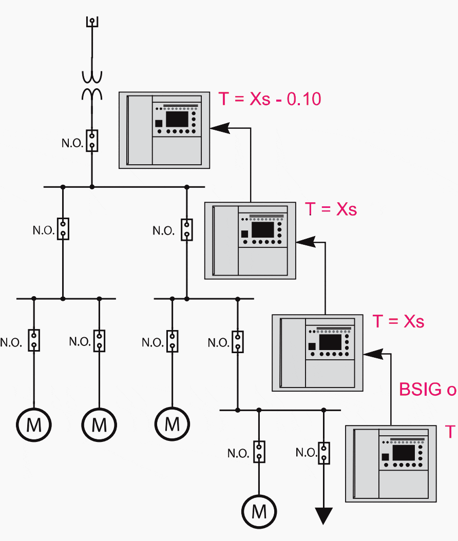
2. Radial distribution with use of zone selective interlocking
(T: protection setting time. As an approximation for definite time curves, this is assumed to be equal to the protection tripping time).


When a fault appears, the protection units that detect it block the upstream protection units. The protection unit furthest downstream trips since it is not blocked by another protection unit.
The delays are to be set in accordance with the device to be protected.
In this example, if the fault clearing time for the protection device furthest downstream is Xs = 0.2 s, the fault clearing time at the source is T = Xs – 0.1 s = 0.1 s.
Reference // Sepam series 80 protective relays – Instruction Bulletin


Very useful…
Thanks….
much thanks
we need to planing the small project for PFC on 10 KV with 2.2 MVAR to improve the the PF from 0.92 to 0.96
with considered the Max Active Power is 8 MW.
please if you can offering the the Technically/commercial that it will be good
W B R
Eng Mohamed Abd elatty
00201004602668 Mohamed.abdelatty@scc-eg.com
I would love to become a paying member. But I refuse to be extorted into participating with PayPal. This is just a non-starter for me due to fraud against me through their company. I won, they lost, but I will NEVER associate with them again and you shouldn’t either. All I want to do is pay with a CC, and join, but you won’t let me without PayPal. Why?
Useful information for me