
Low Voltage Fuses
The simplest overcurrent protective devices
The simplest of all overcurrent protective devices are fuses. A fuse is an overcurrent protective device with a circuit-opening fusible part that is heated and severed by the passage of the overcurrent through it.
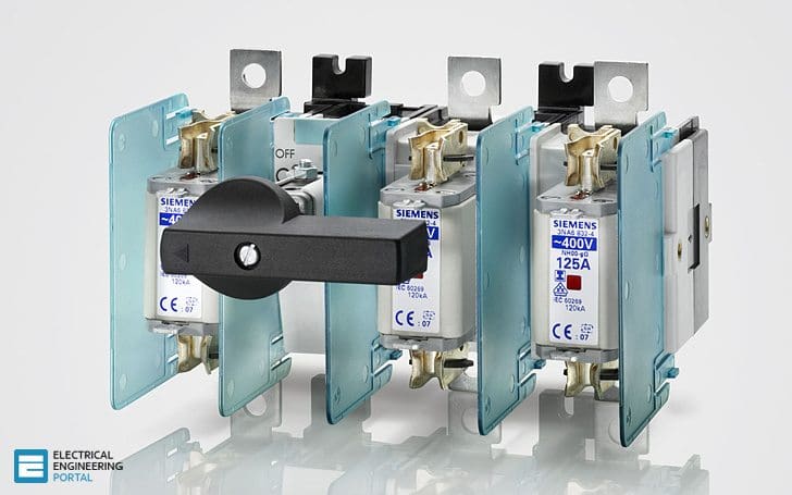 Low-voltage disconnect switch with fuses max. 800A, 690V (photo credit: DirectIndustry.com)
Let’s talk about ten important definitions that are of interest for low voltage fuses //
- Ampere rating
- Current-limiting fuse
- Dual-element fuse
- I2t
- Interrupting rating
- Melting time
- Peak let-through current (Ip)
- Time delay
- Total clearing time
- Voltage rating
1. Ampere rating
The RMS current that the fuse can carry continuously without deterioration and without exceeding temperature rise limits. In accordance with NEC article 210.20 a fuse (or any branch-circuit overcurrent device) should not be loaded continuously to over 80% of its ampere rating unless the assembly, including the fuse and enclosure, is listed for operation at 100% of its rating.
Go back to LV Fuse Definitions ↑
2. Current-limiting fuse
A current-limiting fuse interrupts all available currents its threshold current and below its maximum interrupting rating.
A current-limiting fuse limits the clearing time at rated voltage to an interval equal to or less than the first major or symmetrical loop duration. It limits peak let-through current to a value less than the peak current that would be possible with the fuse replaced by a solid conductor of the same impedance.
Go back to LV Fuse Definitions ↑
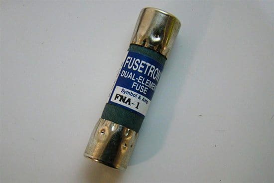
3. Dual-element fuse
A cartridge fuse having two or more current-responsive elements in series in a single cartridge. The dual-element design is a construction technique frequently used to obtain a desired time-delay response characteristic.
Go back to LV Fuse Definitions ↑
4. I2t
A measure of heat energy developed within a circuit during the fuse’s melting or arcing. The sum of melting and arcing I2t is generally stated as total clearing I2t.
Go back to LV Fuse Definitions ↑
5. Interrupting rating
The rating based upon the highest RMS current that the fuse is tested to interrupt under the conditions specified.
Go back to LV Fuse Definitions ↑
6. Melting time
The time required to melt the current-responsive element on a specified overcurrent.
Go back to LV Fuse Definitions ↑
7. Peak let-through current (Ip)
The maximum instantaneous current through a current-limiting fuse during the total clearing time.
Go back to LV Fuse Definitions ↑
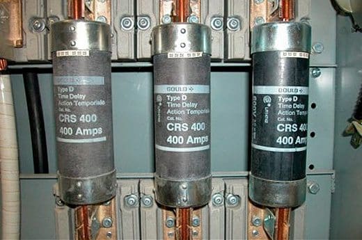
8. Time delay
For Class H, K, J, and R fuses, a minimum opening time of 10s to an overload current five times the ampere rating of the fuse, except for Class H, K, and R fuses rated 0-30 A, 250 V, in which case the opening time can be reduced to 8s.
For Class G, Class CC, and plug fuses, a minimum time delay of 12s on an overload of twice the fuses’ ampere rating.
Go back to LV Fuse Definitions ↑
9. Total Clearing time
The total time between the beginning of the specified overcurrent and the final interruption of the circuit, at rated voltage.
Go back to LV Fuse Definitions ↑
10. Voltage Rating
The RMS voltage at which the fuse is designed to operate. All low voltage fuses will operate at any lower voltage (note that this is characterized as AC or DC, or both).
Go back to LV Fuse Definitions ↑
Fuses, like most protective devices, exhibit inverse time-current characteristics. A typical fuse time-current characteristic is shown in Figure 1.
Logarithmic scales are used for both the time and current axes, in order to cover a wide range.
The characteristic represents a band of operating times for which the lower boundary is the minimum melting time curve, above which the low voltage fuses can be damaged. The upper boundary is the total clearing time curve, above which the fuse will open. For a given fault current, the actual fuse opening time will be within this band.
Table 1 – Low Voltage fuse classes //
In some cases the fuse average melting time only is given. This can be treated as the fuse opening time with a tolerance of ±15%. The -15% boundary is the minimum melting time and the +15% boundary is the total clearing time. Note that the time-current characteristic does not extend below 0.01 seconds. This is due to the fact that below 0.01 seconds the fuse is operating in its current-limiting region and the fuse I2t is of increasing importance.
The time-current characteristic curves are used to demonstrate the coordination between protective devices in series. The basic principle of system protection is that for a given fault current ideally only the device nearest the fault opens, minimizing the effect of the fault on the rest of the system.
This principle is known as selective coordination and can be analyzed with the use of the device time-current characteristic curves.
Because the time bands for the two fuses do not overlap, these are coordinated for all operating times above 0.01 seconds.
It can also be stated that these two sets of fuses are coordinated through approximately 4200 A, since at 4200 A Fuse A has the potential to begin operating in its current-limiting region. Fuse B has the potential to begin operating its current-limiting region at 1100 A. For currents above approximately 4000 A, therefore, both sets of fuses have the potential to be operating in the current-limiting region.
When both sets of fuses are operating the current-limiting region the time-current curves cannot be used to the determine coordination between them.
Instead, for a given fault current the minimum melting I2t for Fuse A must be greater than the maximum clearing I2t for Fuse B. In practice, instead of publishing I2t data fuse manufacturers typically publish ratio tables showing the minimum ratios of fuses of a given type that will coordinate with each other.
Low voltage fuse AC interrupting ratings are based upon a maximum power factor of 0.2, corresponding to a maximum X/R ratio of 4.899. In order to evaluate a low voltage fuse’s interrupting rating on a system with a higher X/R ratio the system symmetrical fault current must be multiplied by a multiplying factor:
where:
The available symmetrical fault current multiplied by the multiplying factor (MULT) per formula above can be compared to the fuse interrupting rating.
The use of low voltage fuses requires a holder and a switching device in addition to the fuses themselves. Because they are single-phase devices, a single blown fuse from a three-phase set will cause a single-phasing condition, which can lead to motor damage.
Replacing fuses typically requires opening equipment doors and/or removing cover panels.
Also, replacement low voltage fuses must be stocked to get a circuit with a blown fuse back on-line quickly. For these reasons, the use of low voltage fuses in modern power systems is generally discouraged. For circuit breakers that have a short-time rating.
Reference // System Protection – Bill Brown, P.E., Square D Engineering Services
Related electrical guides & articles


Edvard Csanyi
Hi, I'm an electrical engineer, programmer and founder of EEP - Electrical Engineering Portal. I worked twelve years at Schneider Electric in the position of technical support for low- and medium-voltage projects and the design of busbar trunking systems.I'm highly specialized in the design of LV/MV switchgear and low-voltage, high-power busbar trunking (<6300A) in substations, commercial buildings and industry facilities. I'm also a professional in AutoCAD programming.
Profile: Edvard Csanyi

I would love to read more about your articles.
Boa noite senhores, pretendo representar a vossa empresa e produtos. Solicito uma representaçáo em Angola e enviar-me listas de preços a grosso com modalidades de pagamentos. Obrigado.
I would love to read more about your articles. Can you please email me.
Can you send me this arquive?
Tks
i like to read it.so kindly send it to my email.