
Substation Assessment
This technical article presents the shorten version of the report of an on-site assessment at the 33/11 kV Shatt Al Arab substation built in Iraq back in 2005. The assessment covered all work completed at that time, so it wasn’t a complete substation commissioning.
 Example of 33/11 kV substation on-site assessment report
Work Completed
Work completed at the time included the construction of the 33/11 kV substation switchgear facility, guardhouse, fencing, exterior lighting, and installation of two 33kV to 11kV transformers (31500 kVA), two auxiliary transformers, neutral grounding system, 11 kV switchgear, and 33 kV switchgear.
The installation of substation electrical equipment was completed prior to site assessment. High voltage power to the facility was not connected at the time of the visit. Therefore, operation of the systems could not be assessed.
Required design drawing and specifications included:
- Plot plan for the substations and associated feeders
- Single-line diagrams including protective devices
- Substation yard steel structural support shop drawings
- Substation civil and site drainage drawings
- Substation yard and building foundation drawings
- Main transformer foundation and fire wall drawings
- Substation building architectural and structural drawings
- Substation building equipment layout
- Substation grounding grid drawings
- Substation raceway layout drawings
- Substation building plumbing, electrical, fire protection, and HVAC drawings
- Underground feeder plan and sections
- Cable schedule
- Three-line diagrams
- DC schematic diagrams
- Circuit breakers, re-closers, line switchers, line sectionalizers, switchgear control and relaying wiring and connection drawings
- Protection relay settings and coordination studies
- Load flow and short circuit calculations
- Catalog cuts of major equipment items
- Construction of substation building
- Construction of perimeter fencing, gates, exterior lighting, and guardhouse
- Delivery and installation of substation equipment
1. Construction of substation building
The contract and approved design included new construction of a substation building to house the 33 kW switchgear, 11 kW switchgear, and associated monitoring and control equipment. Requirements included office space, a bathroom facility, HVAC systems, fire alarm, internal lighting, and a septic system.
The on-site assessment verified the construction of the facility was complete and that the construction appeared to be consistent with the contract and design requirements.
2. Construction of perimeter fencing, gates, exterior lighting, and guardhouse
The contract and approved design included the new construction of a perimeter fence with entrance gates, guardhouse, and exterior lighting.
The 90% design drawings required a perimeter fence on reinforced concrete footings, block construction with exterior stucco and paint. Two iron entry/exit gates were included in the perimeter fence design.
Design drawings required the installation of exterior light poles on a reinforced concrete foundation.
The on-site assessment verified the construction of the guardhouse, exterior fence, and exterior lighting was completed and the construction appeared to be consistent with the contract and design requirements.
3. Delivery and installation of substation equipment
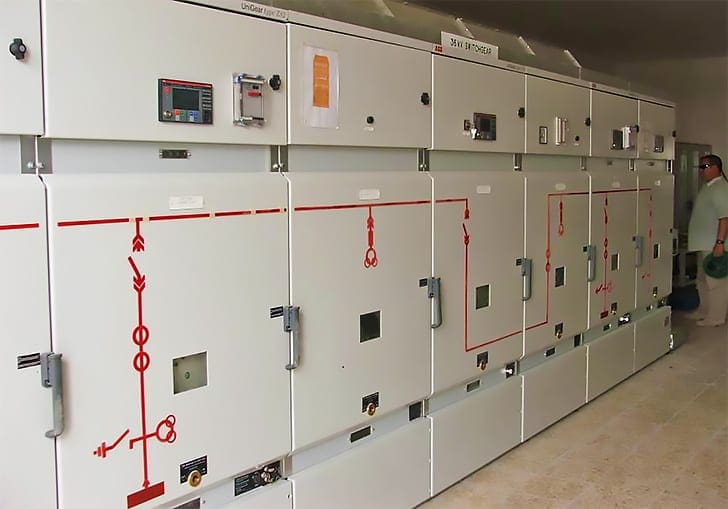
3.1 One 33 kV switchgear
The contract and design required the purchase of a 33 kV switchgear and installation of the switchgear into the newly constructed substation building.
Details from the associated factory nameplate were not obtained during the site assessment. However, the equipment and installation appeared to be consistent with the contract, design, and specifications.
Figure 1 shows site photo of the 33 kV switchgear located inside the substation building.
3.2 One 11 kV switchgear
The contract and design required the purchase of an 11 kV switchgear and installation of the switchgear into the newly constructed substation building. The 90 % design and associated specifications required a 22 bay unit with switchboard rating of 12 kV, 2000A, and 31.5 kA, 3 seconds.
The on-site assessment verified the installation of the 11 kV switchgear. Details from the associated factory nameplate were not obtained during the site assessment. However, the equipment and installation appeared to be consistent with the contract, design, and specifications.
Figure 2 shows the photo of 11 kV switchgear located inside the substation building.

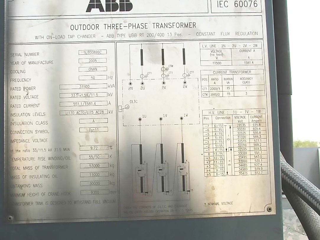
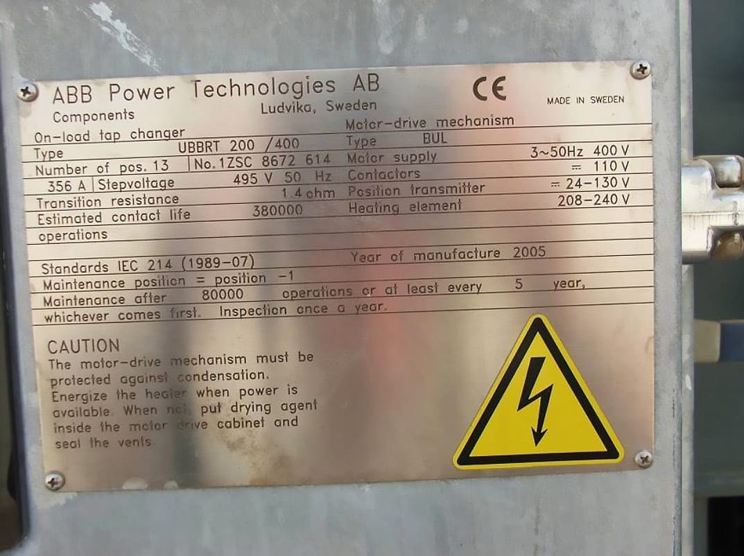
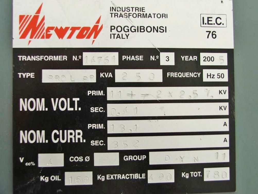
3.3 Two 33 kV to 11 kV transformers
The contract and design required the purchase of two 33 kV to 11 kV transformers and installation of concrete pads, firewalls and the transformers onto the pads. The 90% design and associated specifications required two transformers with on-load tap changers, with rated power of 31,500 kVA and rated voltage of 33 (+5,-7)×1.5%/11.5 kV be installed.
The on-site assessment verified the installation of two 33 kV to 11kV transformers on concrete pads with firewalls between the two transformers.
The on-load tap changer nameplate lists the company name as ABB Power Technologies AB, type UBBRT 200/400.
The equipment and installation appeared to be consistent with the contract, design, and specifications.
Figure 3 shows the photo of the factory nameplate of one of the two 33 kV to 11 kV transformers. Figure 4 shows the factory nameplate of one of the two on-load TAP changers.
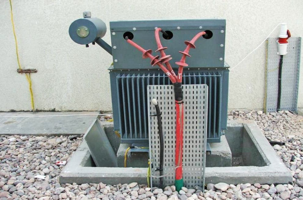
3.4 Two 11 to 0.4 k auxiliary transformers
The contract and design required the purchase and installation of two 11 kV to 0.4 kV auxiliary transformers. The 90% design and associated specifications required the two transformers to be rated at 250 kV.
The on-site assessment verified the installation of two 11 kV to 0.4 kV transformers on concrete pads.
Figure 5 shows the photo of one of the two installed 11 kV to 0.4 kV auxiliary transformers. Figure 6 shows the associated factory nameplate.
The equipment and installation appeared to be consistent with the contract, design, and specifications.
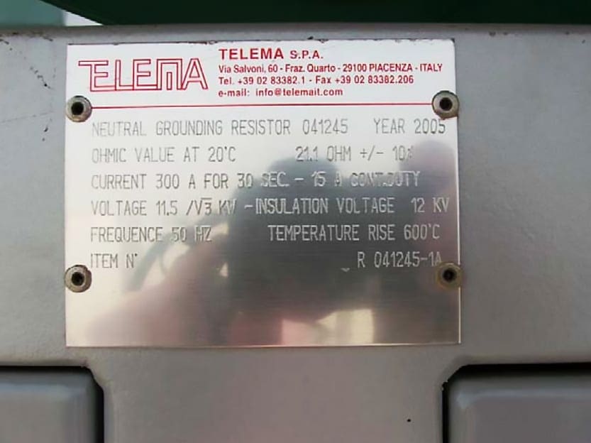
3.5 Grounding system
The contract and design required the purchase of two neutral grounding units and installation of the units. The 90% design and associated specifications required a neutral earthing resistor of 300 A rated current for 30 seconds rated time.
The on-site assessment verified the installation of two grounding units
Figure 7 shows the photo of one of the two installed neutral grounding units. Figure 8 shows the associated factory nameplate.
The equipment and installation appeared to be consistent with the contract, design, and specifications.

Source: Report of site assessment Shatt Al Arab Substation Basrah, Iraq
Related electrical guides & articles


Edvard Csanyi
Hi, I'm an electrical engineer, programmer and founder of EEP - Electrical Engineering Portal. I worked twelve years at Schneider Electric in the position of technical support for low- and medium-voltage projects and the design of busbar trunking systems.I'm highly specialized in the design of LV/MV switchgear and low-voltage, high-power busbar trunking (<6300A) in substations, commercial buildings and industry facilities. I'm also a professional in AutoCAD programming.
Profile: Edvard Csanyi

Very professional useful summary
Thank you Halid.
Thanks for sharing.
very informative article. Thanks
Ju falemderoj për kontributin tuaj.
Respekte Përparimi
THANKS A LOT FOR YOU . . YOU HELP ME SO MUCH TO INCREASE MY KNOWLEDGE ABOUT MY JOP .FOR MOOR SUCCESSES S WITH BEST REGARD
Great work , I know this SS , Thanks for sharing
Thank you .
Its a very elaborative report encompassing the each component of the susbstation,if it is possible send me the detailed commissioning procedure as well to my e mail address.
Looking forward towards your input.
This is a very good article thank you.
Thanks for sharing