Done on the HV winding
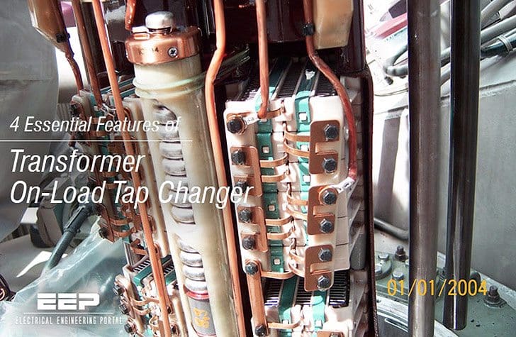
On-load tap changers (or circuit tap changers), as the name suggests, permit tap changing and hence voltage regulation with the transformer on-load.

Tap changing is usually done on the HV winding for two reasons:
- Because the currents are lower, the tap changer contacts, leads, etc., can be smaller.
- As the HV winding is wound outside the LV winding, it is easier to get the tapping connections out to the tap changer.
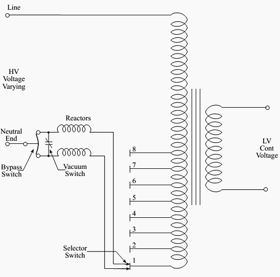
Figure 1 below shows the connections for an on-load tap changer that operates on the HV winding of the transformer.

The tap changer has four essential features:
1. Selector Switches
These switches select the physical tap position on the transformer winding and, because of their construction, cannot and must not make or break the load current.
2. Reactors
The load current must never be interrupted during a tap change.
Therefore, during each tap change, there is an interval where two voltage taps are spanned. Reactors (inductors) are used in the circuit to increase the impedance of the selector circuit and limit the amount of current circulating due to this voltage difference. Under normal load conditions, equal load current flows in both halves of the reactor windings and the fluxes balance out giving no resultant flux in the core.
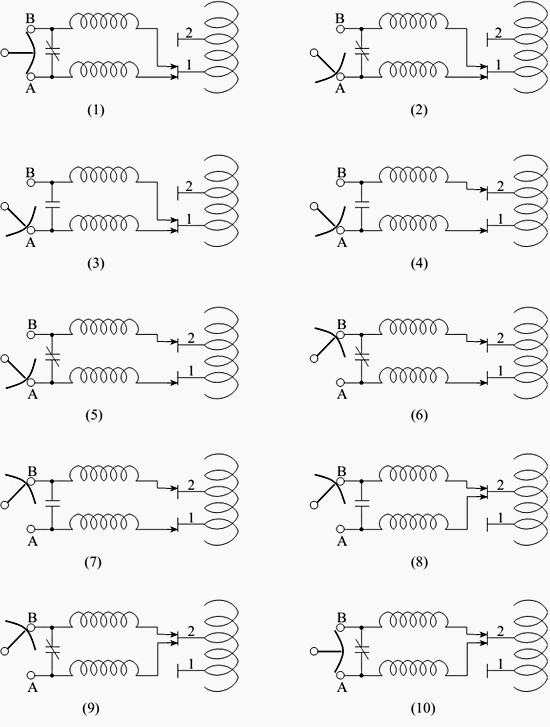
During the tap change, the selector switches are selected to different taps (see Figure 2) and a circulating current will flow in the reactor circuit. This circulating current will create a flux and the resulting inductive reactance will limit the flow of circulating current.
3. Vacuum Switch
This device performs the duty of a circuit breaker that makes and breaks current during the tap changing sequence.
4. Bypass Switch
This switch operates during the tap changing sequence but, at no time, does it make or break load current, though it does make before break each connection.
An example of the tap changing sequence is detailed in Figure 2 (diagrams 1 through 10). Table 1 describes the sequence of operations for the tap changer of Figure 2 to change from tap 1 to tap 2. Changing to any other tap position is done similarly with the selector switch always moving sequentially (i.e., it is impossible to go from tap 1 to tap 3 directly, the order must be tap 1, tap 2, then tap 3).
The sequence of operation is mechanically linked, orinterlocked, to ensure that all contacts always operate in their correct order. Any failure of the operating mechanism can result in severe damage to the transformers and tap changers.
Table 1 – Description of Tap Changing Sequence for Figure 1
| No. | Details of Tap-Changer operation |
| 1 | Present position – tap changer selected to tap 1, bypass switch in, A + B, home position. |
| 2 | Bypass switch selects lower circuit arm. |
| 3 | Vacuum switch opens, removing load current from upper circuit arm freeing one half of selector switch for move. |
| 4 | As there is no load current on upper arm of selector switch, it moves to tap 2. |
| 5 | Vacuum switch closes – both selector switches onload, circulating current is limited by reactors. |
| 6 | Bypass switch selects upper arm circuit arm. No arcing occurs as vacuum switch is closed and in parallel. |
| 7 | Vacuum switch opens, removing load current from lower circuit arm, freeing lower selector switch for move. |
| 8 | As there is no load current on lower arm of selector switch, it moves to tap 2. |
| 9 | Vacuum switch closes – both selector switches onload, in parallel, on tap 2. |
| 10 | With vacuum switch closed and selector switch on a single tap, the bypass switch can now return to its home position. Both reactor circuits stay normally in parallel. The tap change is now complete. |

The previous example describes one type of on-load tap changer. There are several other types inuse however, which may differ significantly from the type described.
Function Principle of the OLTC (Video)
Cant see this video? Click here to watch it on Youtube.
Reference: Science and Reactor Fundamentals – Electrical CNSC Technical Training Group


What Precaution must be taken before Operating Tap Changer?
What is the main difference between Diverter type and Selector type OLTCs?
The diverter style is usually a high speed resistance switching style LTC that drops in place from the top of a transformer. Usally round. Only the diverter is removed for maintenance and the selector components share space with the transformer winding connections in the transformer.
The selector style is usally welded compartment in front of transformer that uses a reactor and vacuum bottles for switching. All three phases are located in this oil compartment and its usually on the low side. These LTCs are usally located on the distribution side of the grid.
A very one sided POV from an American engineer. The world mainly uses resistor type OLTC’s and have done so for 90 odd years. The largest producers of OLTC’s – Reinhausen and ABB offer some very good insight to operation of OLTC’s, but if you are an engineer involved with transformers and don’t understand these principles, maybe further training is needed rather than posting stupid questions on internet forums.
I believe that USA still follows reactor type OLTC whereas rest of the world has changed over to high speed resistor type OLTC, Please add to the article above explaining these two technologies and their pros & cons (or success and failure rates).
I want to know the full detail of online tape changer so pls tell about it
Thank you for this article on Tap Changer Operation. I am trying to understand this statement more clearly. “Reactors (inductors) are used in the circuit to increase the impedance of the selector circuit and limit the amount of current circulating due to this voltage difference”. I believe I understand how the fluxes cancel under normal load, but don’t understand how the voltage difference causes this impedance to increase?
Can you clarify this or point me in the right direction please?
How can find the tap value?
What is the value of one tap in LOTC Transformer…..
Often this is around 0.375% per step. There are usually 33 positions (16 above, one at and 16 below).
OLTC function has been very clearly explained.Thanks to Edward
I wanted to know load flow study of a power plant network with an example.
I wanted to know more about Electrical Engineering.
I would like to receive news regarding electrical engineering and more detailed calculations
Eep is an platform to know electrical engineering in a simple way