Current drawn by the insulation
When DC voltage is applied to an insulation, the electric field stress gives rise to current conduction and electrical polarization. Consider an elementary circuit as shown in Figure 1 below, which shows a DC voltage source, a switch, and an insulation specimen.
However, this current immediately drops in value, and then decreases at a slower rate until it reaches a nearly constant value.
The current drawn by the insulation may be analyzed into several components as follows:
- Capacitance charging current
- Dielectric absorption current
- Surface leakage current
- Partial discharge current (corona)
- Volumetric leakage current
1. Capacitance charging current
The capacitance charging current is high as the DC voltage is applied and can be calculated by the formula:


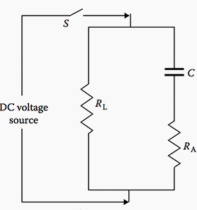

- C represents charging current
- RA represents absorption current
- RL represents volumetric leakage current (dielectric loss)
where:
- ie is the capacitance charging current
- E is the voltage in kilovolts
- R is the resistance in megohms
- C is the capacitance in microfarads
- t is the time in seconds
- e is Napierian logarithmic base
Test readings should not be taken until this current has decreased to a sufficiently low value.
2. Dielectric absorption current
The dielectric absorption current is also high as the test voltage is applied and decreases as the voltage application time increases, but at a slower rate than the capacitance charging current. This current is not as high as the capacitance charging current.
The absorption current can be divided into two currents called reversible and irreversible charging currents. This reversible charging current can be calculated by the formula:
ia = VCDT−n
where:
- ia is the dielectric absorption current
- V is the test voltage in kilovolts
- C is the capacitance in microfarads
- D is the proportionately constant
- T is the time in seconds
- n is a constant
Again, sufficient time should be allowed before recording test data so that the revers- ible absorption current has decreased to a low value.
3. Surface leakage
The surface leakage current is due to the conduction on the surface of the insulation where the conductor emerges and points of ground potential.
This current is not desired in the test results and should therefore be eliminated by carefully cleaning the surface of the conductor to eliminate the leakage paths, or should be captured and guarded out of the meter reading.
4. Partial discharge current
The partial discharge current, also known as corona current, is caused by overstressing of air at sharp corners of the conductor due to high test voltage. This current is not desirable and should be eliminated by the use of stress control shielding at such points during tests.
5. Volumetric leakage current
The volumetric leakage current that flows through the insulation volume itself is of primary importance. This is the current that is used to evaluate the conditions of the insulation system under test. Sufficient time should be allowed for the volumetric current to stabilize before test readings are recorded.
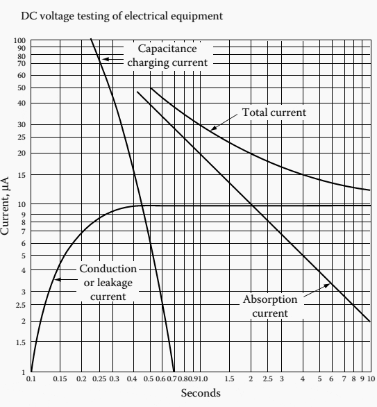
The total current, consisting of various leakage currents as described above, is shown in Figure 2.

Reference // Electrical Power Equipment Maintenance and Testing – Paul Gill





Hi ! I like your articles & I am always reading for my some elcetrical job work , when there are some doubt while doing testing , installation & Commmissioning heavy Electrical Control Equipments.
Thanks & Regards,
Santosh .
Hi, I liked your article very much and I’m sharing this on a FB group MeteringCurry ( on.fb.me/1ZvG4Rx ) Hope it’s ok with you…
Very good article but I suspect the source impedance of the Test Voltage has been left out of the equation.
Settling time on Insulation Measurements is sometimes up to 15-20 seconds.
How to test insulation of wires & cables using fluke 1507..brand.? 2. How to analyze & determine the quantities ,measurements in electrical building drawingdrawing in a simple way?