
Solidly-grounded Wye System
The solidly-grounded system is the most common system arrangement, and one of the most versatile. The most commonly-used configuration is the solidly-grounded wye, because it will support single-phase phase-to neutral loads.
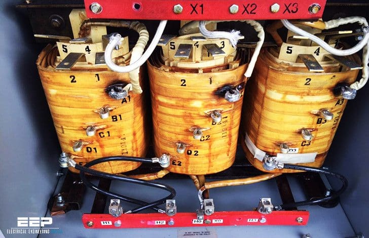
The solidly-grounded wye system arrangement can be shown by considering the neutral terminal from the wye system arrangement to be grounded. This is shown in Figure 1 below.

Several points regarding Figure 1 can be noted.
First, the system voltage with respect to ground is fixed by the phase-to-neutral winding voltage. Because parts of the power system, such as equipment frames, are grounded, and the rest of the environment essentially is at ground potential also, this has big implications for the system.
The operation of a single-phase load connected between one phase and neutral will be the same on any phase since the phase voltage magnitudes are equal.
This system arrangement is very common, both at the utilization level as 480 Y/277 V and 208 Y/120 V, and also on most utility distribution systems.
While the solidly-grounded wye system is by far the most common solidly-grounded system, the wye arrangement is not the only arrangement that can be configured as a solidly grounded system.
Solidly-grounded Delta System
The delta system can also be grounded, as shown in Figure 2 below. Compared with the solidly-grounded wye system of Figure 1 this system grounding arrangement has a number of disadvantages. The phase-to-ground voltages are not equal, and therefore the system is not suitable for single-phase loads. And, without proper identification of the phases there is the risk of shock since one conductor, the B-phase, is grounded and could be mis-identified.
This arrangement is no longer in common use, although a few facilities where this arrangement is used still exist.

The delta arrangement can be configured in another manner, however, that does have merits as a solidlygrounded system. This arrangement is shown in Figure 3. While the arrangement of Figure 3 may not appear at first glance to have merit, it can be seen that this system is suitable both for three-phase and single-phase loads, so long as the single-phase and three-phase load cables are kept separate from each other.
Note that the phase A voltage to ground is 173% of the phase B and C voltages to ground. This arrangement requires the BC winding to have a center tap.

Ground Fault
A common characteristic of all three solidly-grounded system shown here, and of solidly-grounded systems in general, is that a short-circuit to ground will cause a large amount of short-circuit current to flow.
The voltage and current on the other two phases are not affected. The fact that a solidly-grounded system will support a large ground fault current is an important characteristic of this type of system grounding and does affect the system design. Statistically, 90-95% of all system short-circuits are ground faults so this is an important topic.

A solidly-grounded system is very effective at reducing the possibility of line-to-ground voltage transients.
However, to do this the system must be effectively grounded. One measure of the effectiveness of the system grounding is the ratio of the available ground-fault current to the available three-phase fault current. For effectively-grounded systems this ratio is usually at least 60%.
Most utility systems which supply service for commercial and industrial systems are solidly grounded. Typical utility practice is to ground the neutral at many points, usually at every line pole, creating a multi-grounded neutral system. Because a separate grounding conductor is not run with the utility line, the resistance of the earth limits the circulating ground currents that can be caused by this type of grounding.
Because separate grounding conductors are used inside a commercial or industrial facility, multi-grounded neutrals not preferred for power systems in these facilities due to the possibility of circulating ground currents.
In general, the solidly-grounded system is the most popular, is required where single-phase phase-to-neutral loads must be supplied, and has the most stable phase-to-ground voltage characteristics.
However, the large ground fault currents this type of system can support, and the equipment that this necessitates, are a disadvantage and can be hindrance to system reliability.
Reference: System Grounding – Bill Brown, P.E., Square D Engineering Services
Related electrical guides & articles


Edvard Csanyi
Hi, I'm an electrical engineer, programmer and founder of EEP - Electrical Engineering Portal. I worked twelve years at Schneider Electric in the position of technical support for low- and medium-voltage projects and the design of busbar trunking systems.I'm highly specialized in the design of LV/MV switchgear and low-voltage, high-power busbar trunking (<6300A) in substations, commercial buildings and industry facilities. I'm also a professional in AutoCAD programming.
Profile: Edvard Csanyi

People are getting shocked when they are touching two different pieces of equipment, I traced down the ground on one piece of equipment and found out that is came loose from the wire nut down line, is this common. This transformer is a 240 three phase system with a neutral and if you touch each leg to ground you get different voltages.
This is all about the solidly grounded wye connected transformer. We all knew that for a balance Wye connected transformer, the voltage across the neutral line connected by a cable to a solidly ground port is “ZERO”. Say I have a 115kV/13.8kv step down transformer and I have made a solid ground system at the 13.8kV side, Then to detect ground fault current I put a Current transformer say 1000/5, @1KV rated voltage while the cable I used is 8kV XLPE cable. Is there a problem on this even though I did not rate my CT to 8kV? Your opinion is highly appreciated.
Thank you, for the much needed information. I do have a question when reading a transformer with a meter how do you test between phases and your neutral to determine whether it’s a wye our a delta transformer and on which side hi our low ?
thank you for this informative article, what are the delta grounded system over wye one?
and it the delta grounded system suits three phase loads?
What are the basic differences between IEC60364 and AS3000? Can IEC60364 be acceptable globally or regional standards are better?
Thank you for tackling this topic…this would surely be a great help in my work environment.. In a distribution utility.
It’s true that star pont solidly grounded is better from voltage stability point of view. But if not properly maintained there will be catastrophic impact during over loading conditions. So all time there must be a support system to maintain resistance almost to ground level. I always suggest star point solid earth circuit to the system must be twice the phase/line conductors.
While agreeing with Mr Subar’s comments, I would like to suggest that just doubling the conductor size may be insufficient for keeping touch and step potentials below lethal levels.
While it is easy to generalise, part of ant rigorous design must include touch and step potential calculations for individual installations.