
Differential relays take a variety of forms, depending on the equipment they protect. The definition of such a relay is “one that operates when the vector difference of two or more similar electrical quantities exceeds a predetermined amount. It will be seen later that almost any type of relay, when connected in a certain way, can be made to operate as a differential relay. In other words, it is not so much the relay construction as the way the relay is connected in a circuit that makes it a differential relay.
Most differential-relay applications are of the “current-differential” type. The simplest example of such an arrangement is shown in Fig. 14. The dashed portion of the circuit of Fig. 14 represents the system element that is protected by the differential relay. This system element might be a length of circuit, a winding of a generator, a portion of a bus, etc.
A current transformer (CT) is shown in each connection to the system element. The secondaries of the CTÕs are interconnected, and the coil of an overcurrent relay is connected across the CT secondary circuit.
This relay could be any of the a-c types that we have considered.

Now, suppose that current flows through the primary circuit either to a load or to a short circuit located at X. The conditions will be as in Fig. 15. If the two current transformers have the same ratio, and are properly connected, their secondary currents will merely circulate between the two CT’s as shown by the arrows, and no current will flow through the differential relay.

But, should a short circuit develop anywhere between the two CT’s, the conditions of Fig. 16 will then exist. If current flows to the short circuit from both sides as shown, the sum of the CT secondary currents will flow through the differential relay. It is not necessary that short-circuit current flow to the fault from both sides to cause secondary current to flow through the differential relay. A flow on one side only, or even some current flowing out of one side while a larger current enters the other side, will cause a differential current.
In other words, the differential-relay current will be proportional to the vector difference between the currents entering and leaving the protected circuit; and, if the differential current exceeds the relay’s pickup value, the relay will operate.

It is a simple step to extend the principle to a system element having several connections. Consider Fig. 17, for example, in which three connections are involved.

It is only necessary, as before, that all the CT’s have the same ratio, and that they be connected so that the relay receives no current when the total current leaving the circuit element is equal vectorially to the total current entering the circuit element.
The principle can still be applied where a power transformer is involved, but, in this case, the ratios and connections of the CTÕs on opposite sides of the power transformer must be such as to compensate for the magnitude and phase-angle change between the power transformer currents on either side. This subject will be treated in detail when we consider the subject of power-transformer protection.
A most extensively used form of differential relay is the “percentage-differential” type. This is essentially the same as the overcurrent type of current-balance relay that was described earlier, but it is connected in a differential circuit, as shown in Fig. 18.

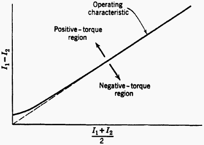
The differential current required to operate this relay is a variable quantity, owing to the effect of the restraining coil. The differential current in the operating coil is proportional to I1 – I2, and the equivalent current in the restraining coil is proportional to (I1 + I2)/2, since the operating coil is connected to the midpoint of the restraining coil; in other words, if we let N be the number of turns on the restraining coil, the total ampere-turns are I1N/2 + I2N/2, which is the same as if (I1 + I2)/2 were to flow through the whole coil.
The operating characteristic of such a relay is shown in Fig. 19. Thus, except for the slight effect of the control spring at low currents, the ratio of the differential operating current to the average restraining current is a fixed percentage, which explains the name of this relay. The term “through” current is often used to designate I2, which is the portion of the total current that flows through the circuit from one end to the other, and the operating characteristics may be plotted using I2 instead of (I1 + I2)/2, to conform with the ASA definition for a percentage differential relay.
The advantage of this relay is that it is less likely to operate incorrectly than a differentially connected overcurrent relay when a short circuit occurs external to the protected zone.
Current transformers of the types normally used do not transform their primary currents so accurately under transient conditions as for a short time after a short circuit occurs.
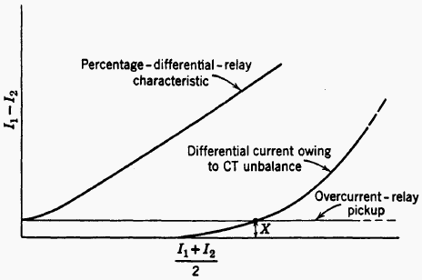
This is particularly true when the shortcircuit current is offset. Under such conditions, supposedly identical current transformers may not have identical secondary currents, owing to slight differences in magnetic properties or to their having different amounts of residual magnetism, and the difference current may be greater, the larger the magnitude of short-circuit current. Even if the short-circuit current to an external fault is not offset, the CT secondary currents may differ owing to differences in the CT types or loadings, particularly in power-transformer protection. Since the percentage-differential relay has a rising pickup characteristic as the magnitude of through current increases, the relay is restrained against operating improperly.
Figure 20 shows the comparison of a simple overcurrent relay with a percentage-differential relay under such conditions. An overcurrent relay having the same minimum pickup as a percentage-differential relay would operate undesirably when the differential current barely exceeded the value X, whereas there would be no tendency for the percentage-differential relay to operate.
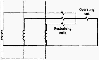
Percentage-differential relays can be applied to system elements having more than two terminals, as in the three-terminal application of Fig. 21. Each of the three restraining coils of Fig. 21 has the same number of turns, and each coil produces restraining torque independently of the others, and their torques are added arithmetically.
The percent-slope characteristic for such a relay will vary with the distribution of currents between the three restraining coils.
Percentage-differential relays are usually instantaneous or high speed. Time delay is not required for selectivity because the percentage-differential characteristic and other supplementary features to be described later make these relays virtually immune to the effects of transients when the relays are properly applied. The adjustments provided with some percentage-differential relay will be described in connection with their application.
Several other types of differential-relay arrangements could be mentioned. One of these uses a directional relay. Another has additional restraint obtained from harmonics and the d-c component of the differential current. Another type uses an overvoltage relay instead of an overcurrent relay in the differential circuit. Special current transformers may be used having little or no iron in their magnetic circuit to avoid errors in transformation caused by the d-c component of offset current waves. All these types are extensions of the fundamental principles that have been described, and they will be treated later in connection with their specific applications.
There has been great activity in the development of the differential relay because this form of relay is inherently the most selective of all the conventional types. However, each kind of system element presents special problems that have thus far made it impossible to devise a differential-relaying equipment having universal application.






Find the mistake in this statement: “if we let N be the number of turns on the restraining coil, the total ampere-turns are I1N/2 + I2N/2, which is the same as if (I1 + I2)/2 were to flow through the whole coil.”
R: I1N/2+I2N/2 = (I1+I2)*N/2
why we dont use differential relay on distribution transformer
The article is very informative. It would be better if you had explained about Busbar differential protection too.
A very nice and informative share to revice the concepts…
Thanks
Thank you very much! I tried to summarize almost all applications and forms of using differential relays.
BR