
Fault loop and fault current
The use of protective conductors linking all the exposed conductive parts of all equipment creates a circuit called the “fault loop” designed for circulation of the fault current that arises following an insulation fault.
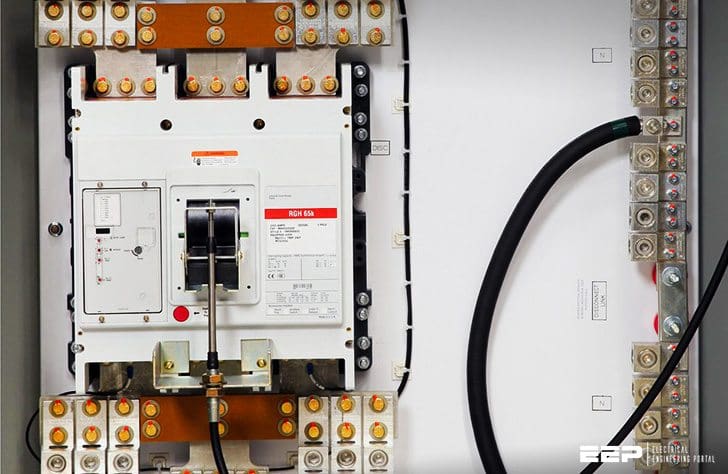 Protection from fault current by automatic power supply disconnection (photo credit: PSI Control Solutions)
The fault current may or may not be carried to earth, depending on the neutral earthing system, but in all cases the objective is to keep the voltage of the exposed conductive parts to a value below the conventional limit voltage of 50V.
The fault current value will determine the breaking device to use in each case:
- TN system – Overcurrent device to break a high current similar to a short circuit
- TT system – Residual current device to break a low fault current
- IT system – No need to break the 1st fault current, as it is very low
The application of the protective measure of disconnecting the power supply involves the use of class I equipment. For devices, this requirement generally simply means connection of the protective conductor. For the creation of assemblies, the application of class I construction rules must be subject to a number of precautions.
Class I Assemblies
All parts that can be directly accessed by the user are considered to be exposed conductive parts, even if they are covered with paint or coatings, unless these prove to have insulating qualities that are known and tested at the thickness applied (example: film bonded to the part).
The concept of exposed conductive parts is also extended to all metal parts that are inaccessible to the user but can be accessed by a worker, even a qualified worker, including after dismantling, due to the fact that their layouts or dimensions lead to an appreciable risk of contact (examples: rails, plates, device supports, etc.).
It is also extended to intermediate metal parts that are inaccessible but are in mechanical contact with the exposed conductive parts, due to the fact that they can spread a voltage (example: mechanism transmissions).
All the protective conductors are connected to a general equipotential link to which the metal trunking and conductive elements from outside the building are also connected. The equipotential link reduces the touch voltage in the event of a fault, whatever the earth connection scheme (neutral earthing system).
Operating principle of protection in TT configuration
In the event of an insulation fault in a receiver, the fault current If (I fault) flows in the circuit called the fault loop. This comprises the impedance of the fault on the exposed conductive part of the receiver, the connection of this exposed conductive part to the protective conductor, the protective conductor itself, and its earth connection (RA).
The loop is closed by the transformer windings and the power supply circuit. Logically, therefore, the impedance of the loop should be calculated from all of the elements in series which make up this loop.
The condition RA × If < 50V must be satisfied for alternating current installations. The sensitivity threshold IΔn of the residual current device is chosen so that IΔn<50/RA.

Operating principle of protection in TN configuration
In the event of a fault at any point in the installation affecting a phase conductor and the protective conductor or an exposed conductive part, the power supply must be disconnected automatically within the specified disconnection time t and the condition Zs × Ia < U0 must be fulfilled.

Where:
- Zs – impedance of the fault loop including the power supply line, the protective conductor and the source (transformer windings).
- Ia – operating current of the protective device in the specified time.
- U0 – nominal phase/earth voltage.
The maximum times should be applied to circuits that might supply Class I mobile devices (generally, all power outlets). In practice, these times are observed by the use of non-delayed circuit breakers.
This formula verifies that the ratio of the protective conductor’s impedance to the total fault loop impedance is such that the potential of the exposed conductive part at fault will not exceed 50 V, but it does not verify that disconnection occurs within the required time limit.
Operating principle of protection in IT configuration
At the first fault, the current If is limited by the sum of the resistances of the power supply earth connections (RB), the exposed conductive parts (RA), and the impedance (Z). In the example below, this gives:
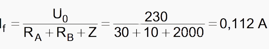
The non-disconnection condition is verified, whilst ensuring that the current will not raise the exposed conductive parts to a potential greater than the limit voltage UL. SWe must therefore have:
RA × If < 50 V, i.e., in the example, 30 × 0.112 = 3.36 V
The exposed conductive parts will not reach a dangerous voltage, and non-disconnection is authorised. To ensure continuity of operation, the fault notified by the permanent insulation controller (PIC) must be found and eliminated as quickly as possible by qualified personnel.
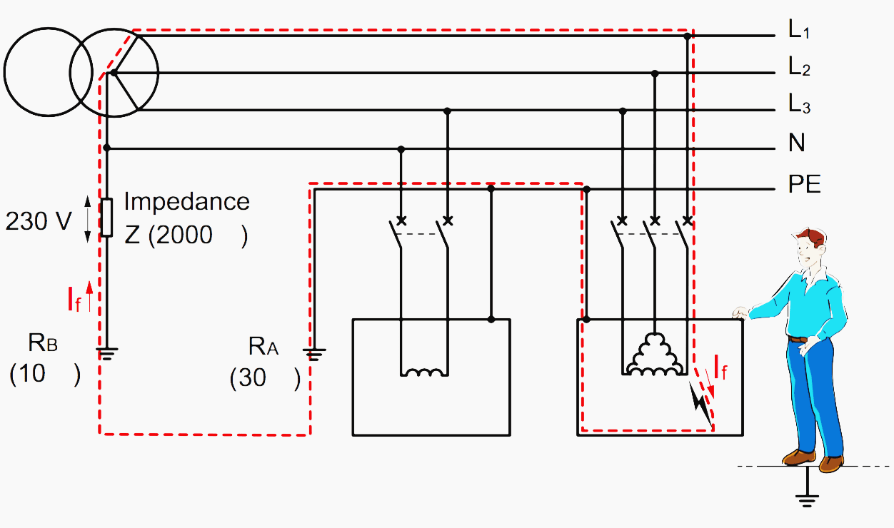
At the second fault affecting another phase, on the same exposed conductive part or a different one, a loop is formed by the exposed conductive parts and the supply conductors. It will result in the flow of a high current (short circuit), which can be eliminated via the conditions shown in the TN or the TT diagram.
The lengths of protected line are reduced accordingly. In the event of a fault, the potential of the neutral could go as high as the phase at fault (simple voltage). The potential of the other phases will tend to rise to the value of the compound voltage.
That is why it is advisable not to supply devices between phase and neutral in an IT configuration and therefore not to distribute the neutral.

Maximum disconnection times t0 (s) – iEc 60364-4-41
| System | 50V < U0 ≤ 120V | 120V < U0 ≤ 230V | 230V < U0 ≤ 400V | U0 ≤ 400V | ||||
| a.c. | d.c. | a.c. | d.c. | a.c. | d.c. | a.c. | d.c. | |
| TT | 0,3 | (1) | 0,2 | 0,4 | 0,07 | 0,2 | 0,04 | 0,1 |
| TN and IT (2e fault) | 0,8 | (1) | 0,4 | 0,5 | 0,2 | 0,4 | 0,1 | 0,1 |
(1) Disconnection may be required for reasons other than protection against electric shock
Reference // Electrical hazards and protection persons by Legrand
Related electrical guides & articles


Edvard Csanyi
Hi, I'm an electrical engineer, programmer and founder of EEP - Electrical Engineering Portal. I worked twelve years at Schneider Electric in the position of technical support for low- and medium-voltage projects and the design of busbar trunking systems.I'm highly specialized in the design of LV/MV switchgear and low-voltage, high-power busbar trunking (<6300A) in substations, commercial buildings and industry facilities. I'm also a professional in AutoCAD programming.
Profile: Edvard Csanyi

The article has given important information regarding earthing of electrical equipment to ensure users safety against fatal electric shocks.