
Estimated Study Time: 6 minutes
ATS to Emergency / Standby Source
Multiple utility services may be used as an emergency or standby source of power. Required is an additional utility service from a separate source and the required switching equipment.
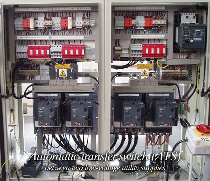
Figure 1 shows automatic transfer between two low-voltage utility supplies. Utility source 1 is the normal power line and utility source 2 is a separate utility supply providing emergency power. Both circuit breakers are normally closed. The load must be able to tolerate the few cycles of interruption while the automatic transfer device operates.
Automatic switching equipment may consist of three circuit breakers with suitable control and interlocks, as shown in Figure 2.
Circuit breakers are generally used for primary switching in which the voltage exceeds 600 V. They are more expensive but safer to operate, and the use of fuses for overcurrent protection is avoided.
If either supply is not able to carry the entire load, provisions must be made to drop noncritical loads before the transfer takes place. If the load can be taken from both services, the two R circuit breakers are closed and the tie circuit breaker is open.
This mode of operation is generally preferred by the supplying utility and the customer.
The three circuit breakers are interlocked to permit any two to be closed but prevent all three from being closed. The advantages of this arrangement are that the momentary transfer outage will occur only on the load supplied from the circuit that is lost, the loads can be balanced between the two buses, and the supplying utility doesn’t have to keep track of reserve capacity for the emergency feeder.
However, the supplying utility may not allow the load to be taken from both sources, especially because a more expensive totalizing meter may be required. A manual override of the interlock system should be provided so that a closed transition transfer can be made if the supplying utility wants to take either line out of service for maintenance or repair and a momentary tie is permitted.
If the utility will not permit dual or totalized metering, the two sources must be connected together to provide a common metering point and then connected to the distribution switchboard. In this case, the tie circuit breaker can be eliminated and the two circuit breakers act as a transfer device (sometimes called a transfer pair).
Under these conditions, the cost of an extra circuit breaker can rarely be justified.
The arrangement shown in Figure 2 only provides protection against failure of the normal utility service.
Continuity of power to critical loads can also be disrupted by:
- An open circuit within the building (load side of the incoming service)
- An overload or fault tripping out a circuit
- An electrical or mechanical failure of the electric power distribution system within the building
It may be desirable to locate transfer devices close to the load and have the operation of the transfer devices independent of overcurrent protection. Multiple transfer devices of lower current rating, each supplying a part of the load, may be used rather than one transfer device for the entire load.
The arrangement shown in Figure 2 can represent the secondary of a double-ended substation configuration or a primary service. It is sometimes referred to as a “main-tie-main” configuration.
Availability of multiple utility service systems can be improved by adding a standby engine-generator set capable of supplying the more critical load. Such an arrangement, using multiple automatic transfer switches, is shown in Figure 3 .
Reference: ELECTRICAL ENGINEER’S PORTABLE HANDBOOK – ROBERT B. HICKEY, P.E. (Purchase book at Amazon)
Related electrical guides & articles


Edvard Csanyi
Hi, I'm an electrical engineer, programmer and founder of EEP - Electrical Engineering Portal. I worked twelve years at Schneider Electric in the position of technical support for low- and medium-voltage projects and the design of busbar trunking systems.I'm highly specialized in the design of LV/MV switchgear and low-voltage, high-power busbar trunking (<6300A) in substations, commercial buildings and industry facilities. I'm also a professional in AutoCAD programming.
Profile: Edvard Csanyi

I need control circuit wiring diagram of automatic change-over using 2 motorised mccb
I need diagrams to add 2 ATS Switches for, and a generator at, a secondary building. The generator will be providing backup power for that same building as well as the Main building which both 120/240V residential services are fed from. The ATS Switches will be one at each end of the underground conduit feeding the secondary building. Both distribution (Main) panels in the buildings were wired from the secondary of the Meter after the main Service Drop. I hope someone will send diagrams my way. It will be much appreciated, as I have been unable to find them on the internet through regular searches. Thank You!
I NEED A SCHEMATIC DIAGRAM FOR THREE INCOMER 3PHASE AND 1 OUTGOING
Dear all I want to know about ADS so can you help me please
THANKS TO EDWARD , EXCELLENT DESCRIPTION
Hi
What difference it makes when an ATS using standard motor operated circuit breakers(ACB or MCCB) used instead of UL spec ATS like ASCO. Zenith etc..?
Can we provide the interlocking between three circuit breaker in an auto transfer switch. Breaker Q1 form Main Power supply, Breaker Q2 alternate power supply and breaker Q3 Generator Power supply. Interlocking between Q1& Q2 for failure main supply, this Q1 open and Q2 close, and failure of main and alternate supply, under voltage relay on the down stream bus will within less than 5 sec give start signal to Generator and within 30Sec Q3 close and Q1 & Q2 become open. At the resumption of main or alternate supply, the relay sense the voltage on breaker Q1 & Q2 and with certain time delay open breaker Q3 and close wither Q1 or Q2. and after resumption of normal power, a signal should send generator for stop.
dear sirs Can you please share detailed explanation of ATS CONTROLLER for 2 GENSETS + MAINS
The automatic start is designed for automatic starting of one Genset when mains failure.
– if the running Genset shut down to any fault that occurs the other set will automatically start and supply the load.
Thanks & regards
M.Ismael
hello I would like some clarification in reference to the ATS system, in a configuration with two transformers that feed two bars divided by a tie breaker when a main breaker fails the tie breaker closes automatically so that one of the two transformers feed the other bar .
I would like to know if you create a short voltage loss or is the ats system so quick to avoid it?
Dear sir
We have two building, building -1 load 50kw, building -2 load 30kw which is power supply by individual transformer sources.
I want to emergency power back up (when building-1 or building-2 or both load sheding) from a 200 KVA Generator. How i can do it. Please i want to your help.
Note : 1.Two building distance 300ft
2. 200kva generator with 350 Amp ATS set on building 1.
3. Building 2 no generator.
Md. Hafizur Rahman
Bangladesh
DEAR SIR ,
I WILL BE USING TWO TRANSFORMERS ON SITE, CAN YOU SUGGEST ME SHOULD I USE TWO EMERGENCY PANELS & ATS OR CAN IT BE USE BY ONE ?
REGARDS
MOHAMMED
Hi Sir,
Is it possible to connect a back up generator to essential services bus (1) and utility supply to non-essential services bus (2), then use a tie breaker to connect the two buses so whenever the utility fails the tie breaker will disconnect the bus (2) and let essential services run on backup generator.
Thank you.
i want to connect two 11kv voltage sources from different utilities injecting into the same 11kv feeder in run. which type of ATS i can use? is this possible.regards
Thank you for sharing ATS function in detail.
Can you please share detailed explanation of ACB control circuit(internal control wiring of ACB(schneider or siemens ACB) for operation) for 2 incomer 1 bus coupler scheme along with drawing ?
I am little perplexed to do this wiring by myself and need your help. I request you to please briefly explain the sequential operations of different internal elements of Air circuit breaker like spring charge, motor, closing coil, trip coil, anti pump, under voltage relay, SPP and contacts when closing & tripping while operating manually from TNC switch & in Auto mode.
Thanks & regards
Darshan V
Thanks for your blog, as a power engineer I am interested in power transfer between more than one source and the design principle of when they take up load.kindly advise.thanks
You’re welcome Akinola. You didn’t mention the voltage level, but if it’s low voltage, you can take a search for terms ‘transfer switch’ or ‘ats’.
Nice to be your fan.
dear sirs , is there any magazine that i can receive monthly which covers all new news in electric engineering and technology
thanks alot
Can we accept and consider a certain voltage range [say between +/- 10% from utility supply] to enable ATS to changeover to a standby generator. That means the ATS will consider any voltage beyond +/- 10% of utility supply as a blackout condition and automatically changeover to Generator [even when the Utility supply is available, beyond +/- 10% range]
you can do it by adjusting the over and under voltage relay. there are many version of that relay you can consider. But in your case, I think the most suitable one will be the percentage relay
Hello sir
I want you to tell me about ELV system.
can anyone tell me what is the main difference between auto main failure (AMF) and automatic transfer switch (ATS) ???
Hi, I’ve been on a project in parts of africa where the utility supplies 3-phase mains to residential properties. However, for various reasons, the voltage supplied is really low and most of the time is only coming in on one of the phases. The utility company every now and then changes which of the 3 phases has actually got power, and kills off the other two. This happens every day. So the locals have hot-wired their buildings to run on any one of the phases that is currently on. When there is an outage, they look down the street, and if there is any building with the lights on, then they figure there is power in a different phase, so they go to a 3 phase box and pull out a clunky connector and try plugging it into the other remaining 2 phases connectors in turn, until there is power.
Needless to say this is a somewhat dangerous and hair raising experience to watch, especially as the high voltage box in the residence has obviously been rewired locally and there are all sorts of random high voltage wires sticking out in the air. Ironically, safety has probably been assured by the fact that only low voltage is every received from the utility company!
Anyway, my question is, do you know of any switching box/cabinet/thingy that could be re-purposed for this. So that the local in question could turn a lever and try out the 3 phases in turn, without having to open the cabinet and pull out connectors and push them back in. I think that we can safely treat the 3 phase incoming as 3 alternative single phase power sources (as this local situation has been going on for 20 years) and therefore a switching transfer system between 3 mains/utility alternative input sources, with one output would be ideal. However most switching/transfer cabinet solutions i’ve seen assume only 2 AC sources available (mains and generator). Do you have any ideas of a boxed system I could use for this switching ?
Your power is excellent and problem is not with you, problem is your government. And there you can make change over switching of phases to any phases with help of ACBs as your wish list of connections
Hi Edvard,
I have 2 questions
1.What’s the approx delay time (prespecified) in case of Open Delay Transfer?
2.How does ATS detect power restoration?
Having began my journey into the engineering world, I have found this site so much insiteful and knowledge-packed which has always been my companion. Thanks and keep the job going!!
Welcome aboard Daniel!
Hello,
i deal with the same type of ATS and currently having an issue with it. Can you kindly pass me the control circuit diagram for ATS.
Hi Sir,
I have one client which the LV switchboard include two number of 500A MCCB units as the incoming ATS for essential and city main power. During the building power test, the auto mode of ATS system was not fed to essential power when the city power is failed and the generator is up. However, the ATS system is changed to essential power normally by operated manual mode.
Would you have any comment for above issue?
Thanks for your help.
Best regards,
Thank you sir for your effort your really help me.
Dear sir i want know more information regarding this equipment(Switch). i am using a 10KVA inverter on this inverter(Bi directional inverter) i am using 3 HP motor and general load. when Grid supply(Main source) off at that time i want to share inverter load only for 3 HP motor if motor is in ON condition only otherwise i want to work at normal condition . for requirement can i use This switch… please give the answer.
Am an electrical engineering student and working on this electrical filed, Your posts on your Facebook page has been of great importance and help in my practice in my electrical works. Keep it up for good work.
I would like to do an electrical engineering degree online is it possible and with which colleges
Bus transfer in a large plant where there are many induction motors are presented, would be a very difficult job, if the tuning has not be done carefully. Please take care about it. You just need a very intelligent real time simulator to take care of these things.
Dear Sir
WE ARE INTEREST TO DEVELOP Relay Based Control AMF/ATS 100KVA GENSET PANEL IN THIS REGARD WE NEED YOUR HELP TO BE DEVELOPED AND PROVIDING US THE ELECTRICAL DRAWING.
Best Regard
S.M Hashim
Please download POUYA from http://www.intelectri.com and then choose ORDER YOUR OWN network and then put your Single Line Diagram and the associated data there, they will provide you with the design and relay coordination of your plant, while you can also test the system in real time simulator. This is the best choice you can select.
I want to read new technology
Use POUYA software to tune the time of switching.
http://www.intelectri.com
Please visit an actual real time simulation of bus transfer in a water pumping station.