
Estimated Study Time: 5 minutes
Overcurrent protection
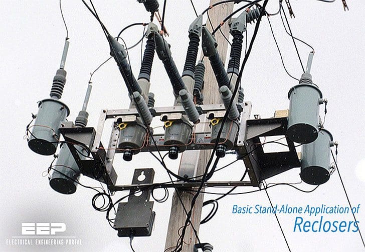
Reclosers are self-contained fault interrupting and reclosing devices, specifically designed for overcurrent protection in secondary distribution systems. Reclosers are situated in selected locations within the overhead distribution network.
With the correct protection setting and MV fuse selection coordination, concerning the whole supply loop from the supplying primary distribution substation feeder to the fuse-protected distribution transformer, it is possible to achieve a discriminative fault isolation function.
The recloser assembly consists of the fault-breaking primary unit, typically pole-mounted with brackets, and a control cabinet mounted near the ground level. Both three-phase and single-phase units are used, depending on the secondary distribution operation and protection philosophy. The current measuring is carried out with internally mounted bushing current transformers.
The switching device is typically either a vacuum-type or oil-type of a circuit breaker with nominal currents up to 1250A and a rated voltage up to 38kV. The breaking capacity of the circuit breaker can reach up to 16kA.
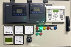
Figure 1 – Typical recloser’s breaking unit (vacuum type) on the left and control cabinet on the right

Automatic fault isolation functionality
Following principal system diagrams describe one basic “stand-alone” application of reclosers.
Furthermore, a solid line marks for an energized line and a dashed line marks for a de-energized line.
In the first diagram, the two feeders are supplied from two separate primary distribution substations with the tie recloser open.

The second diagram shows a permanent fault situation on the first feeder. As a result of the fault, the feeder in the substation has made an unsuccessful autoreclosing attempt and has locked out with the breaker open.

In the third diagram, the sectionalizing recloser has opened, isolating the faulty section of the feeder.

In the fourth diagram, the tie recloser has closed energizing the healthy section of the looped feeder.
Gridshield Recloser Overview (VIDEO)
Reference // ABB’s Distribution Automation Handbook – Elements of power distribution systems
Related electrical guides & articles


Edvard Csanyi
Hi, I'm an electrical engineer, programmer and founder of EEP - Electrical Engineering Portal. I worked twelve years at Schneider Electric in the position of technical support for low- and medium-voltage projects and the design of busbar trunking systems.I'm highly specialized in the design of LV/MV switchgear and low-voltage, high-power busbar trunking (<6300A) in substations, commercial buildings and industry facilities. I'm also a professional in AutoCAD programming.
Profile: Edvard Csanyi

well keep up the good works, very useful information indeed
very good website