
Estimated Study Time: 19 minutes
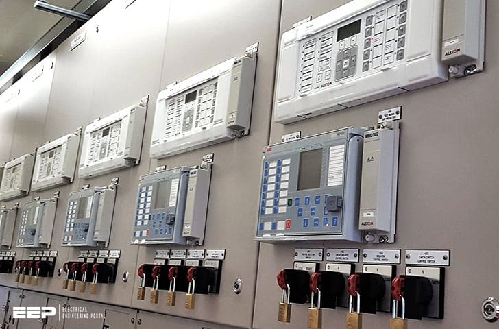
Busbars in T&D substations
Busbars play an important role in power transmission and distribution. They are employed as a central distribution point for all feeders. In the case of a fault, current on the busbar becomes high, resulting to mechanical destruction which would affect all feeders.
 Busbar protection in power transmission and distribution substations
The problem is that the busbars are usually left out without specific protection because it is assumed that they have high reliability. It was feared that if a busbar had a dedicated protection scheme it might mal-operate and end up affecting the whole power system.
The other reason was that back up protection was assumed to be good enough to provide decent bus protection. Due to problems such as loss of loads and long time to clear the faults, when using back up protection, a dedicated busbar protection scheme is required.
When it comes to a dedicated busbar protection the high speed operation, reliability and stability is in demand. Instability of the power system might be caused by case of a failure to trip during an external fault or false tripping during service of the busbar.
This will lead to a complete blackout.
This technical article explains a busbar theory at the distribution network level. It also covers the busbar protection schemes that are currently in use and their operation.
Busbar protection schemes
There are a number of protection schemes designed for busbars. The most used are as follows:
- System protection used to cover busbars
- Frame-Earth Protection
- Differential protection for busbars
- Reverse blocking / interlocking protection
The scheme for a system protection is used at small-size power substations. A detailed explanation of the frame earth protection, differential protection, and reverse interlocking protection for busbars is discussed further.
1. System protection used to cover busbars
The system that is used to cover busbar protection consists of overcurrent or distance protection. Making use of this system the busbar will be inherently protected.
This system also can be used as back up protection by using time grading in a case where slow protection action is required. Time grading ensures that the circuit breaker nearest to the fault always opens first, by choosing an appropriate time setting for each of the relays.
A simple radial distribution system as shown in Figure 0, to illustrate the principle and is well explained in this technical article ‘The fundamentals of protection relay co-ordination and time/current grading principles’.
2. Frame-Earth Protection
Frame earth protection for busbars has been extensively used in the past. This method can be applied to various layouts of busbar protection, each having certain capability.
Frame earth protection schemes are still in existence and provide effective service for busbar protection. Introduction of numerical relays has added to a decline in application of a frame leakage system.
Let’s explain the protection schemes of the following frame-earth protection options:
- Single-busbar frame-earth protection
- Frame-earth protection (sectioned busbars)
- Frame-earth scheme in double bus substation
2.1 Single-Busbar Frame-Earth Protection
This protection scheme in a single busbar layout is seen as an earth fault system and is utilized for measuring currents that flow from the switchgear frame to the earth.
This scheme is designed in such a way that an instantaneous relay as shown in the Figure 1 is energized by the current sensed by the CT that is mounted on the
earthing conductor.
It is critical that the switchgear should be insulated from the ground by making use of concrete as a foundation.
2.2 Frame-Earth Protection (Sectioned Busbars)
This system divides the busbar into sections and the protection is also done separately. This is done by dividing the frame in to sections each using a dedicated earth conductor. Each section consists of a separate CT and a protection relay.
These sections are now treated as separate zones as shown in Figure 2. This system is arranged in such a way that the protective relay only trip when the fault is
within its respective zone.

2.3 Frame-Earth Scheme – Double Bus Substation
In this system protection is provided as single bus insulation with additional trip circuits connected to the auxiliary bus as shown in Figure 3 to operate for all faults.

A check system is used to provide security to the equipment against events caused from operation due to human error or mechanical shock. This check system is not applicable for small equipment.
If the low voltage wiring is faulty the check system must prevent the operation caused by the current passing to earth via the switchgear frame. The operation is provided by energizing the protection relay using the neutral current. If the check system for the neutral is not offered, the frame earth relays will operate after a short time delay.
3. Differential protection for busbars
Differential protection operation directly uses the Kirchhoff’s Current Law where it is required that the currents going into a node are equal to current leaving the node.
When the sum of the currents is not equal to zero by comparing their magnitude or phase the difference is referred as a fault current as shown in Figure 4.
When the busbar has a fault also known as internal fault, the total currents entering it is not equal to zero. Fault current If is the sum of the all currents.
There are numerous methods can be used to apply the scheme.
Figure 5 shows an arrangement where one relay is employed with several CTs connected in parallel. This method is also useful for earth fault protection system for a busbar. An additional protection for phase faults can be achieved by connecting balanced group CTs in each phase in conjunction with three phase element relay as shown in Figure 5 below.
In order to have a good performance for the scheme it is recommended to configure the phase and earth fault settings to be identical.
3.1 High Impedance Differential Protection
High impedance differential protection scheme has been in use for over fifty years because of its robust, fast and secure operation. This scheme makes use of the voltage across the differential junction points.
The disadvantages for the scheme are that it requires dedicated CTs which adds extra cost. During a busbar fault it requires an additional voltage limiting varistor that is utilized to absorb energy.
Take a look explanation in Stephen’s video.
3.2 Low Impedance Differential Protection
Low impedance differential protection scheme do not require dedicated CTs. This scheme has capabilities to tolerate substantial CT saturation during external faults. It also provides relatively high tripping speed.
Introduction of microprocessor based relays makes this scheme to become attractive to most protection engineers because of its advance algorithms for percent differential protection functions.
Re-configuration of busbar protection became less complex. Possibilities of replacing Data Acquisition Units (DAU) in bays by utilizing distribution architectures have become implementable.
Referring to Figure 6 above, input currents defining – through the dynamic bus replica – the bus differential zone, are received by the relay from Current Transformers (CT’s) associated with the power system.
The currents are digitally pre-filtered (block 1) in order to remove the decaying dc components and other signal distortions. The filtered input signals are brought to a common scale taking into account the transformation ratios of the connected CT’s (block 2).
Phasors of the differential zone currents are estimated digitally (block 3) and the differential (block 4) and restraining (block 5) signals are calculated. The magnitude of the differential signal is compared with a threshold and an appropriate flag indicating operation of the unbiased bus differential protection is produced (block 6).
The unsupervised unbiased current differential element operates whenever the measured differential current is above the set value.
The directional element (block 10) supervises the biased differential characteristic when necessary. The current directional comparison principle is used that processes phasors of all the input currents as well as the differential and restraining currents.
The saturation detector (block 9) analyzes the differential and restraining currents as well as the samples of the input currents. This block sets its output flag upon detecting CT saturation.
The output logic (block 11) combines the differential, directional and saturation flags into the unbiased differential operation flag. The applied logic enhances performance of the relay while keeping an excellent balance between dependability/speed and security.
3.3 Differential Protection for Sectionalized Busbars
When a differential protection is employed for sectionalized busbars it is required that divided bus utilizes separate circulating current.
Zones are used to divide the sections and are designed in such a way that they are overlapping across the section switches, so the whole system is protected as shown in Figure 7 below.

In a double busbar layout system the two busbars are handled as separate zones. Where the busbar is coupled, the zones will overlap. This system is designed in such a way that an isolator switch is connected between the busbars.
It must be associated to an appropriate zone by means of early make and late break auxiliary contacts. This is to guarantee that when the isolators are closing, the auxiliary switches operate before the main contacts of the isolator.
When the isolators are opened, their main contacts open before the auxiliary switches. The secondary circuits of the two zones are briefly paralleled and are linked through the circuit isolators during the transfer operation.
3.4 Location of the Current Transformers
In an ideal protection system the zones should overlap and have a separate discrimination protection circuits. The system is designed in such a manner that where the zones overlap there should be a circuit breaker across to cover both zones.
With this system CTs must be installed on both sides of the circuit breaker as shown in Figure 8(a). This is an ideal arrangement for busbar zone protection because it covers all primary circuits.
Figure 8(b) shows an arrangement where the CTs are installed at one side of the circuit breaker. This is not ideal because it leaves a small region of the primary circuit unprotected.
This unprotected region is called short zone.
A special protection needs to be provided to detect faults in the “short zone” and a trip signal to be sent to the next upstream breaker.

4. Reverse blocking / Interlocking protection
In a distribution busbar system traditionally when a fault occurs it was cleared by time delay protection upstream relays. With the introduction of numerical technology a simple protection scheme such as busbar blocking scheme can be applied to protect a distribution system with a single source.
A time grading is required to coordinate these overcurrent relays in order to avoid race conditions.
The advantages for utilizing this scheme are as follows:
- Modifications for the scheme to suit substation extension are easy.
- It utilizes overcurrent elements that are already supplied by the feeder protection relays.
- It requires minimal cost in comparison with the differential protection scheme.
- It has faster fault clearance in comparison to a system that utilizes trip originated by upstream feeder protection.
Interlocked overcurrent schemes, also described as ‘busbar blocking’ or ‘zone sequence interlocking’ schemes can offer economical alternative.
As feeder protection must in any case be installed for all circuits emanating from the busbar, the only additional cost to configure the busbar protection is to design and install the means for the individual relays to communicate peer-to-peer with each other.
References //
- Investigation of the application of IEC 61850 standard in Distribution busbar protection schemes by Mkhululi Elvis Siyanda Mnguni
- An Innovative Low-Impedance Bus Differential Relay: Principles and Applications by GE
- Network Protection & Automation Guide by GE (Alstom Grid)
Related electrical guides & articles


Edvard Csanyi
Hi, I'm an electrical engineer, programmer and founder of EEP - Electrical Engineering Portal. I worked twelve years at Schneider Electric in the position of technical support for low- and medium-voltage projects and the design of busbar trunking systems.I'm highly specialized in the design of LV/MV switchgear and low-voltage, high-power busbar trunking (<6300A) in substations, commercial buildings and industry facilities. I'm also a professional in AutoCAD programming.
Profile: Edvard Csanyi

Dear Professor (Edvard)
I hope this message finds you well.
I found your recent presentation/topic very informative and valuable. If possible, I would greatly appreciate it if you could share a copy of the material you presented.
Thank you very much for your time and support.
For reverse blocking scheme, how can the 50 on feeder distinguish between a fault on busbar and an external fault. For a busbar fault, 50 on the feeder will pickup and block the incomer 50 protection from operating. I think directional overcurrent 67 is required for this scheme to work. Thanks.
Dear sir
Theoretically ok but I don’t know calculation of all protection
Explain the protection of busbar
a 3-phase four wire system is used for lighting. Compare the amount of copper wire required with that of two wire d.c. system with the same line voltage. Assume the same losses and balanced load. The neutral is one half the cross-section of one of the respective outer.
Thanks
very useful article
Great work
Many thanks!
Thank You for sahrig. Can i have a copy. Excellent
Thanks
Can I have one copy
This is an excellent approach in explaining the concept.
Please can I have copy.
Go ahead and download :) The link is at the bottom.
Hi, Edvard,
Very useful document, can I have a copy of this document!
Best regards,
Nguyen Nghi from Vietnam
Sir, Can I have the copy? Thank you
Very apt. But would love to have a copy sent to me on my mail. Thanks
Excellent article. very helpful. i enjoyed it. many thanks.
Chakib Abi -Saab
Caracas, venezuela