
Estimated Study Time: 7 minutes
Installation options for capacitor banks
In an low voltage electrical installation, capacitor banks can be installed at three different levels:
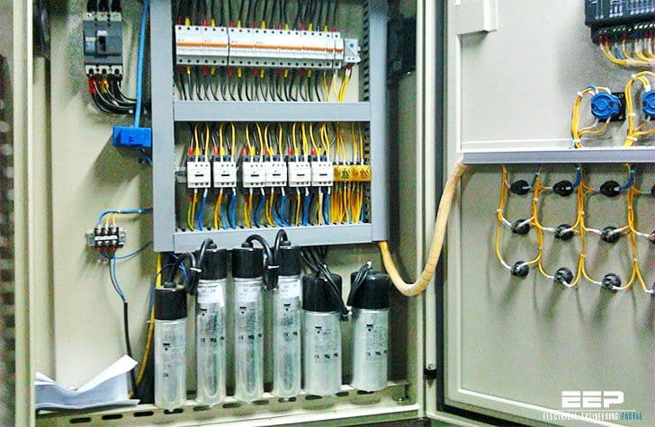
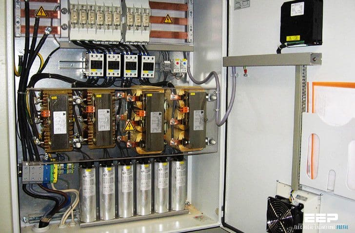 Capacitor banks – installation options, protection and connection (photo credit: power-star.co.za)
After installation ways, we’ll discuss about protection and connection of capacitors banks.
1. Global installation
This installation type assumes one capacitors compensating device for the all feeders inside power substation.
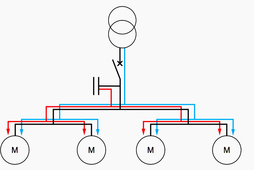
This solution minimize total reactive power to be installed and power factor can be maintained at the same level with the use of automatic regulation what makes the power factor close to the desired one.
What’s good in this solution //
- No billing of reactive energy
- This is the most economical solution, as all the power is concentrated at one point and the expansion coefficient makes it possible to optimise the capacitor banks
- Makes less demands on the transformer
But, the downsides are :
- The losses in the cables (RI2) are not reduced.
- This is not the best solution for large electric systems, especially when the distance between the source and nonlinear receivers is long. The longer distance, the bigger losses in transmission system.
Go back to capacitors installation options ↑
2. Segment (or group) installation
Segment installation of capacitors assumes compensation of a loads segment supplied by the same switchgear. Capacitor bank is usually controlled by the microprocessor based device called power factor regulator.
Beside, segment installation practice demands protection for capacitor banks.
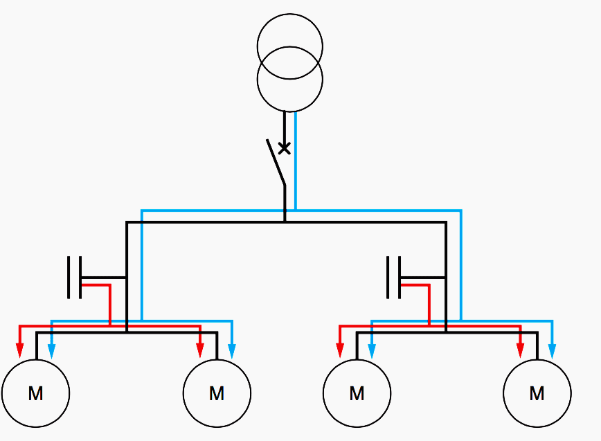
In this case, capacitor banks are connected to the busbars, which supply a group of loads.
What’s good in this solution //
- No billing of reactive energy.
- Makes less demands on the supply feeders and reduces the heat losses in these feeders (RI2) Incorporates the expansion of each sector.
- Makes less demands on the transformer.
- Remains economical.
But, the downside is : – Solution generally used for very widespread factory supplies.
Go back to capacitors installation options ↑
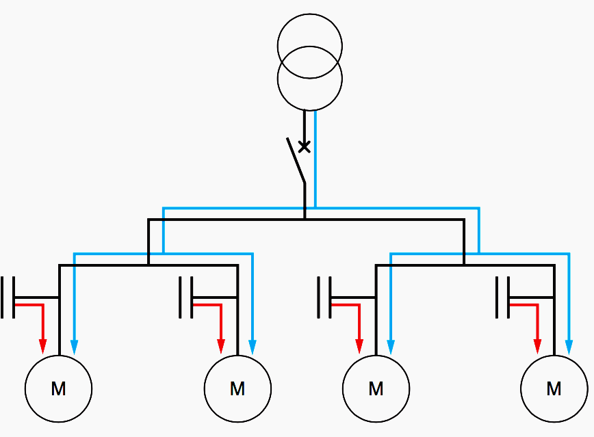
3. Individual (or single) installation
Put in practice by connecting power capacitor directly to terminals of a device that has to be compensated. Thanks of this solution, electric grid load is minimized, since reactive power is generated at the device terminals.
What’s good in this solution //
- No billing of reactive energy
- From a technical point of view this is the ideal solution, as the reactive energy is produced at the point where it is consumed. Heat losses (RI2) are therefore reduced in all the lines.
- Makes less demands on the transformer.
But, the downsides are:
- Capacitor is not being used when the feeder load is not operating.
- Most costly solution, given:
- The high number of installations
- The fact that the expansion coefficient is not incorporated
Go back to capacitors installation options ↑
Protection and connection of capacitors
Operating device
In the case of loads with ultra-fast cycles (welding machines, etc.), the conventional system for operating capacitors (electromechanical contactors) is no longer suitable. High-speed switching compensation systems using solid state contactors are necessary.
The switching current of a capacitor depends on:
- The power of the capacitor
- The short-circuit power of the mains supply to which it is connected
- Whether or not any capacitor banks that have already been activated are present
Contactors are specially designed by contactor manufacturers for operating capacitors and in particular for assembling automatically controlled capacitor banks. These contactors have auxiliary poles combined in series with preload resistors that will limit the inrush current during activation.
Go back to capacitors installation options ↑
Protection
In addition to the internal protection devices incorporated in the capacitor:
- Self-healing metallised film
- Internal fuses
- Overpressure disconnection devices
This protection will be provided by:
- Either a circuit breaker:
- Thermal relay, setting between 1.3 and 1.5 × In
- Magnetic relay, setting between 5 and 10 × In
- Or GI type HRC fuses, rating 1.4 to 2 × In
Example //
In = capacitor nominal current
In = Qc / √3 U
In = 50/1.732 × 0.4 = 72 A
Go back to capacitors installation options ↑
Connection – sizing the cables
Current standards for capacitors are defined so that capacitors can withstand a permanent overcurrent of 30%. These standards also permit a maximum tolerance of 10% on the nominal capacitance.
Cables must therefore the sized at least for: Icable = 1.3 × 1.1 (Inominal capacitor)
i.e. Icable = 1.43 × Inominal
Go back to capacitors installation options ↑
References //
- Reactive energy compensation and power quality monitoring by Legrand
- Reactive Power Compensation – Master thesis by Jakub Kępka at Faculty of Electrical Engineering
Related electrical guides & articles


Edvard Csanyi
Hi, I'm an electrical engineer, programmer and founder of EEP - Electrical Engineering Portal. I worked twelve years at Schneider Electric in the position of technical support for low- and medium-voltage projects and the design of busbar trunking systems.I'm highly specialized in the design of LV/MV switchgear and low-voltage, high-power busbar trunking (<6300A) in substations, commercial buildings and industry facilities. I'm also a professional in AutoCAD programming.
Profile: Edvard Csanyi

Diagram of the capacitor bank
capacitor bank position in main distribution swich gear panel
H t capacitor bank improve ment for transmission line
Excellent effort.
Please I need help on how to connect capacitor bank. Diagrams and real pictures
I would to be your agent in Zambia. Our company is dealing in energy management
Hi Edvard
I read everything in this website about power savers and capacitors .
we have 3 phase electricity line
can you tell me how i can make capacitors bank for this electricity
regards
When selecting operating devices, the user must be made aware of the choice of equipment available (for operating capacitors). Can’t understand properly this line. Can u explain pls? TIA.
Great article!! detailed one…thanks for posting!
how much is the cost benefice
having capacitors.spare parts+failures+maintenece VS paying the reactive power bill
Edvard, would you alter the first line of the example to read: In = capacitor current [i.e. not ‘voltage’]
Hooh, thanks David! Typo fixed!