
Secure & Dependable Protection
Protection engineers have a variety of communication channels to use for relay protection. This is a field in itself, and is very important for a discussion of the protective systems. Historically and currently, channels generally have been the weakest link in the protection chain.
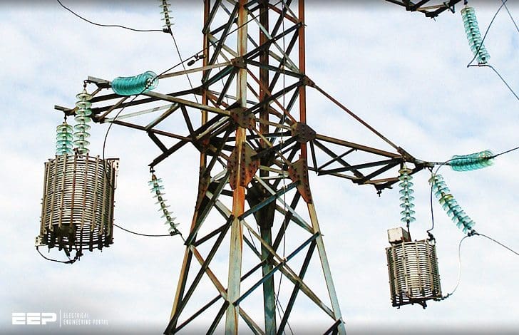 Communication Channels As The Weakest Link In The System Protection Chain (on photo: Electricity pylon with line traps and optical fiber cable)
Tremendous progress has been made from the early applications in the 1930s to the quite sophisticated and highly reliable equipment available in recent times. This is a specialized field, and applications for protection should be made by specialists in this area, who are familiar with the protection requirements.
Good engineering for channels is mandatory for secure and dependable protection, as it is for the relay protection part.
Contents:
- Power-Line Carrier: On-Off or Frequency-Shift
- Pilot Wires – Audio Tone Transmission
- Pilot Wires – 50 Hz Or 60 Hz Transmission
- Digital Channels
- Summary
1. Power-Line Carrier – On-Off or Frequency-Shift
Beginning in the early 1930s radio frequencies between 50 and 150 kHz were superimposed on the power lines for pilot protection. They were originally used in an on–off mode and, as the art progressed, frequency-shift became available.
These are known as power-line carrier channels (PLCC) and are in wide use with frequencies between 30 and 300 kHz. Figure 1 illustrates a typical channel of this type.
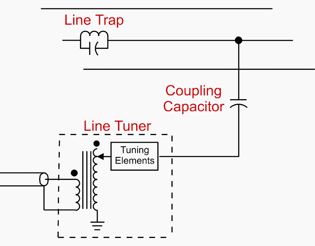
In the past, 100 W transmitters were available, but they are not in common use currently. The RF signal is connected to the high-voltage line through a line tuner and coupling capacitor, as shown. The tuner, normally mounted at the base of the coupling capacitor unit, cancels the capacitance of the coupling capacitor unit.
This provides essentially a low-impedance resistive path for efficient transfer of RF signals to and from the line section.
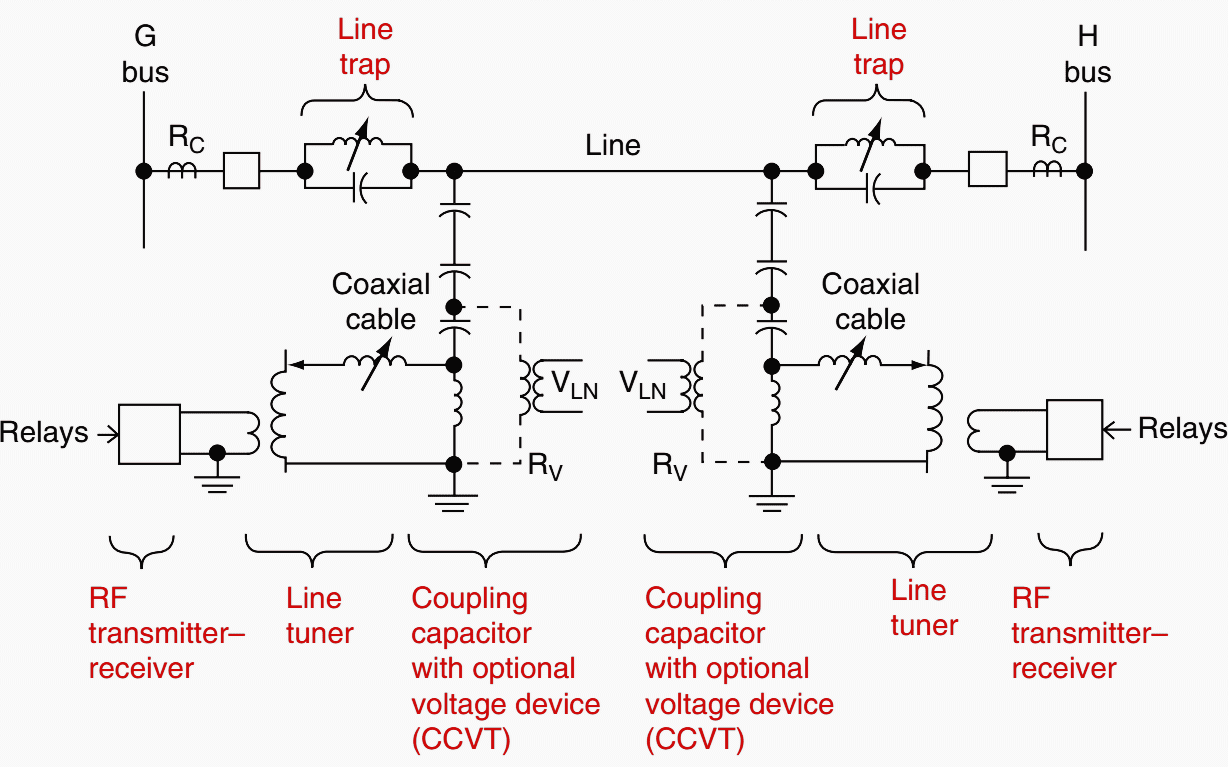
At the remote end, the RF energy passes through similar equipment to the receiver. The transmitter–receiver may be tuned to the same frequency or to different frequencies, which may require a double-frequency tuner.
The inductance between the coupling capacitor and ground presents a high impedance to the RF signal, but low impedance to the system 50 or 60 Hz. This unit may also supply secondary voltage as Coupling capacitor voltage devices (CCVTs), in which case, three are used to connect individual phases, and only one is used for coupling, as shown.
A line trap is connected in the high-voltage line at each terminal just external to the RF path. It is tuned to provide a high RF impedance, to minimize signal loss into the buses and associated systems, and to prevent external ground faults from potentially shorting out the signal.
Traps are available for tuning to a single frequency, double (two) frequencies, or to a broad band of RF frequencies. They are designed to carry a 50 to 60 Hz-load current continuously at low loss, and to withstand the maximum fault current that can pass through the line.
Although the RF signal is introduced to one of the phases, it is propagated by all three-phase conductors. There have been several occasions when the accidental coupling to different phases at the two terminals has gone unnoticed for several years because an adequate signal was received.
In fact, the signal may be greater when coupled to different phases.
Model analysis has provided an important modern tool for predicting carrier performance and the best method of coupling and transmission. This is important, especially for long lines.
Overhead power lines tend to have a characteristic impedance (Z0) between 200 and 500 V phase-to-ground and 400–488 V between phases. The carrier equipment and coupling particularly match these values for maximum power transfer of the RF.
Taps and discontinuities, particularly if they are at quarter wavelengths, can result in high signal losses. The RF signals should be selected to avoid these problems.
Carrier transmitter–receivers are operated on–off, frequency-shift with mark-space signals, or single sideband, depending on the design and application.
Fault arc noise has not been a problem or a significant factor in the use of power-line carrier for protection. Disconnect switches with currents less than 200 A can cause operation of carrier on–off receivers, but this does not impair the protection used with this type of equipment.
More Information: Power-Line Carrier Channel & Application Considerations For Transmission Line Relaying
2. Pilot Wires – Audio Tone Transmission
Audio tones in the range of 1000–3000 Hz are used for protection. They are more compatible for use over leased telephone facilities and, therefore, they are frequently applied over these channels for protection.
he protection hazards and solutions outlined earlier are applicable. When used, neutralizing transformers should be able to pass the audio-frequencies with low losses.
Frequency-shift, on–off, and pulse-code equipment is available.
3. Pilot Wires – 50 Hz Or 60 Hz Transmission
One of the early and still used channels is a twisted pair of ‘‘telephone’’ wires to provide a low-voltage, low-power continuous circuit between the protected zone terminals.
Preferably, wires on the order of AWG 19 are desired both for mechanical strength and to provide loop that is not more than about a 2000 V for two terminals or not more than 500 V per leg for three-terminal applications.
The problems that are experienced with pilot wires result from induction from lightning or a paralleled power circuit, insulation stress from a rise in station ground-mat voltage during faults, direct physical contact by lightning or with the power circuit, physical damage by insulation failure, or gunfire directed at overhead circuits.
4. Digital Channels
In recent years, digital channels are increasingly used for pilot relaying communications. Some of the types of digital channels that are used for this function include:
- Dark fiber (dedicated fiber-optic cable),
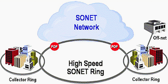
- Multiplexed fiberoptic systems (T1 and SONET),
- Digital microwave,
- Radio links, and
- 56 kbps phone lines (Digital Data Service).
Digital microwave can be point-to-point or used within a SONET ring. Digital communication systems are a study in themselves and are beyond the scope of this article.
It is important, however, for protection engineers to become familiar with this area as digital communication systems continually play a large role in modern protective systems.
The large amount of control wiring that was required within substations for protection and control is replaced in many cases with digital communication systems with the application of microprocessor based relaying. Practically all modern microprocessor relays have built-in digital communication capability and ports for sending and receiving digital messages.
With respect to pilot relay systems, the optimal digital channel performance can be obtained from a dedicated fiber pair. The dedicated pair is virtually immune from electrical interference, has a very low bit error rate, and a very short end-to-end data delay time.
Such application, however, is very expensive and can be prone to long outages if the fiber is cut.
Multiplexed digital networked systems offer the advantage of very low outage rates. In such systems, if a path is lost, an alternate route is automatically and quickly inserted. Such systems are also more economical than dark fiber because up to 24 channels can be multiplexed on a single fiber pair.
Digital microwave is suitable for pilot relaying schemes in that the channel delay times are very short (500–600 msec).
A concern with using digital microwave is its tendency to fade during inclement weather conditions – it is during these types of conditions that faults are most likely to occur on the power system!
Some of the important parameters that need to be considered when applying digital communication systems in pilot relay schemes include the following:
1. Delay time from end-to-end
The pilot system must be capable of dealing with variations in delay times that exist in many digital systems. A difference could exist between the delay time involved in sending a signal and that involved with receiving a signal.
Delay times can also change when alternate paths are inserted.
2. Interruptions to the communication channel
The system must be designed to be capable of resynchronization following a switching operation on the communication network.
3. Excessive bit errors.
High attenuation caused by long distances can result in bit error rates that are very high for obtaining satisfactory operation of a pilot system. Moreover, copper links can exist within communication networks resulting in the possibility of electrical interference.
Replacement of wire pairs used in electromechanical pilot wire schemes must have very short end-to-end delays. These older pilot wire systems were not designed to account for any channel delay.
NOTE: – In such applications, channel delays less than 1 msec are desirable and channels with delays more than 2 msec should not be considered.
Periodic interruptions, long delay times (greater than 20 msec), and asymmetrical delays are other problems that have been encountered when attempted to apply such systems in relaying schemes.
Summary
The channels used for protective relaying are as follows:
- Pilot wires – A twisted wire pair for transmitting 60, 50 Hz DC between terminals. Originally telephone pairs were used, privately owned dedicated pairs are preferred.
- Audio frequency tones – On–off or frequency-shift types over wire pairs, power-line carrier, or microwave.
- Power-line carrier – Radio frequencies between 30 and 300 kHz, transmitted chiefly over high-voltage transmission lines. On–off or frequency-shift types are used.
- Microwave – Radio signal between 2 and 12 GHz, transmitted by line of-sight between terminals. Multiple channels with protection by a subcarrier or audio tone.
- Digital Channel – Types of media include dedicated optical fiber (dark fiber) or multiplexed networks. Multiplexed networks include T1 multiplexing, SONET, digital microwave, and radio links.
When owned by the utility, fiber-optic cables can be imbedded in the ground wire, wrapped around a power cable, or buried along the right-of-way. Digital channels may also be leased from an outside telecommunications company.
Power line carrier in power transmission line (VIDEO)
Reference // Protective Relaying Principles and Applications by J. Lewis Blackburn and Thomas J. Domin (Purchase hardcopy from Amazon)
Related electrical guides & articles


Edvard Csanyi
Hi, I'm an electrical engineer, programmer and founder of EEP - Electrical Engineering Portal. I worked twelve years at Schneider Electric in the position of technical support for low- and medium-voltage projects and the design of busbar trunking systems.I'm highly specialized in the design of LV/MV switchgear and low-voltage, high-power busbar trunking (<6300A) in substations, commercial buildings and industry facilities. I'm also a professional in AutoCAD programming.
Profile: Edvard Csanyi

Minor correction:
“Dark fibre” is not a “dedicated fibre”
It is a fibre that has no signals (light) passing through it .. i.e. it is unused, or spare. It may be terminated into the fibre driver devices at each end but specifically NOT carrying any active system signals other than “driver handshaking”.
Currently, this type of protection is rarely used in transmission line protection
The best in ELECTRICAL ENGINEERING OF THE TIME.