
Estimated Study Time: 4 minutes
")
Electrical and Mechanical Losses
All rotating electrical machines generate heat as a result of the electrical and mechanical losses inside the machine. Losses are high during starting or dynamic braking.
Also, losses usually increase with increased loading. Cooling is necessary to continuously transfer the heat to a cooling medium, such as the air. The different methods of cooling rotating machines are classified in the standards IEC 34.6 and AS 1359.21.
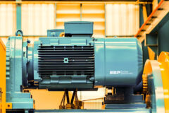
For AC induction motors, cooling air is usually circulated internally and externally by one or more fans mounted on the rotor shaft. To allow for operation of the machine in either direction of rotation, fans are usually of the bi-directional type and made of a strong plastic material, aluminum, or steel.
In addition, the external frames of the motor are usually provided with cooling ribs to increase the surface area for heat radiation.
These are designed to keep the air flow close to the surface of the motor along its entire length, thus improving the cooling and self-cleaning of the ribs. An air-gap is usually left between the ribs and the fan cover for this purpose.
Internally, on smaller TEFC motors, the rotor end-rings are usually constructed with ribs to provide additional agitation of the internal air for even distribution of temperature and to allow the radiation of heat from the end shields and frame.
Special precautions need to be taken when standard TEFC induction motors are used with AC variable speed drives, powered by VVVF converters. For operation at speeds below the rated frequency of 50 Hz, the shaft mounted fan cooling efficiency is lost. For constant torque loads, it is sometimes necessary to install a separately powered forced cooling fan (IC 43) to maintain adequate cooling at low speeds. On the other hand, for prolonged operation at high speeds above 50 Hz, the shaft mounted fan works well but may make excessive noise. Again, it may be advisable to fit a separately powered cooling fan.
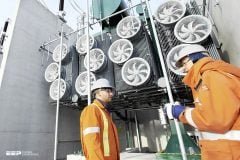
Larger rotating machines can have more elaborate cooling systems with heat exchangers.
The system used to describe the method of cooling is currently being changed by IEC, but the designation system currently in use is as follows:
- A prefix comprising the letters IC (index of cooling)
- A letter designating the cooling medium, this is omitted if only air is used
- Two numerals which represent:
- The cooling circuit layout
- The way in which the power is supplied to the circulation of the cooling fluid, fan, no fan, separate forced ventilation, etc

SOURCE: Practical Variable Speed Drives – Malcolm B.
Related electrical guides & articles


Edvard Csanyi
Hi, I'm an electrical engineer, programmer and founder of EEP - Electrical Engineering Portal. I worked twelve years at Schneider Electric in the position of technical support for low- and medium-voltage projects and the design of busbar trunking systems.I'm highly specialized in the design of LV/MV switchgear and low-voltage, high-power busbar trunking (<6300A) in substations, commercial buildings and industry facilities. I'm also a professional in AutoCAD programming.
Profile: Edvard Csanyi

I am looking for other perspectives/dealings on DC motor cooling. We have an external fan system set up for the motor cooling, the intake air was placed in possibly the worse place to induce air with high contents of corrosive G2 qualities of 5 PPM H2S and is wreaking havoc on the copper. The system has dual filter media elements with PCB (Puracarb) installed, I know the ultimate fix would be to relocate this air intake, this will require an engineering group study and the data to back it before I make that decision. I want to know others experiences and ask the group for references that I could get in contact with to help me with this issue. Thank y’all for taking the time to read!
this site very useful. thanks
I have six 3000hp motor that sit inside of (2) buildings. Would like to install a vent system to move the heat out of the building. Do you help design system like this?
I’m electrical chargeman, need to ask and suggestion or opinion….
Motor
KW: 22
FLA: 33.9
SF: 1.25
Class: F
Motor always run more from FLA (normally 34.5) OL setting 37.8 (110%) from FLA setting.
If continue run the amp more than FLA can effected the motor winding insulation and by the end motor grounded (winding insulation burn out)
please share the answer …you cooperation highly appreciated….
The reference to AS 1359.21 is to the 1974 code that was superseded in 1996 by 1359.106. That code has since been withdrawn. The IEC 60034.6 is the appropriate reference.
I wanted to know how to remove the drive shaft
Hi…
What is MOC (Material of Construction) of Cooling Fan for Hazardous Area (Zone 1), Anti Static & Anti Corrosive?
what is the impact or influance of changing the cooling fan on non -drive end shaft of an vertical electric motor of 225 kw power with another which is not the same and it make noise?
What is the impact of additional cover (normally made of GI sheet) on electrical motor???
Isi ti actually required or just to protect from external environment????
Guys I’m a electrical engineer working in a plant, which has both ac and dc motors. I just want to see how many of u can answet this….
Why even a small ac motor(induction) have ribs on its body for cooling but even the largest of dc motors(we in our plant have upto 1MW DC MOTOR) don’t have ribs for cooling on their body?
DC machines see a DC field in the gap! The stator mounted magnets do not generate any eddy currents which could generate heat. No other heat generating source in the stator (no windings).
P.S.
I am not sure if you asked this because you don’t know ( which is OK to ask ) or, if you trying to sound like a smart ass – in which cases, mission accomplished!
Dear sir,
I’m not confirm about your question but according to me in case of ac motors there are many losses. Such as due to inductance, reactance. Also the tenancy of ac current is to flow from the surface of the conductor. Which tends to reduction in the cross section of conductor and increase in CU losses. Which in case increases heat and hence ac motors requires more cooling than dc.
Please sheare your answer.
Thank you!!!
I like your explanation ,it is short and very vivid