Introduction to non-unit protection
Non-unit protection consists of circuits that measure and compare the voltages and currents at the relaying point. It is able to determine the location of the fault from these values. It generally only responds to faults in one direction.

Non-unit protection is time graded. It is arranged so that the protection within the faulted zone operates first and removes the fault, thus allowing protection in other zones to reset before completing their tripping function.
This contrasts with unit protection which will not operate for a fault outside its zone. Examples of non-unit protection include fuses, overcurrent and distance relays, reclosers, and sectionalisers.
Details of distance protection follow. They include the following critical aspects which should be properly understood in order to later provide a proper setting of a distance relay:
- Voltage
- Current
- Operation
- Grading
- Switched versus full schemes
- Measuring elements
- Close-on fault
- Communication channel
1. Voltage
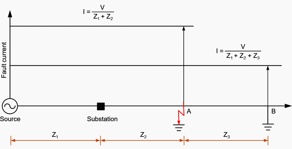
Figure 1 shows that the voltage measured at the substation equals the voltage drop along the line to the fault. The fault is assumed to be a solid fault which reduces the voltage to zero at that point (a reasonable assumption for most fault conditions).
Figure 1 shows that the voltage measured by the distance protection at the substation is higher for the fault at location B than for a fault at location A, that is, V2 is larger than V1.


2. Current
Figure 2 shows that the current measured at the substation varies inversely with the distance along the line to the fault. The nearer the fault is, the lower is the impedance of the line to the fault.
Consequently, the higher will be the fault current.
Figure 1 and Figure 2 above show that if the fault location is moved nearer to the substation, the voltage decreases and the current increases.

3. Operation
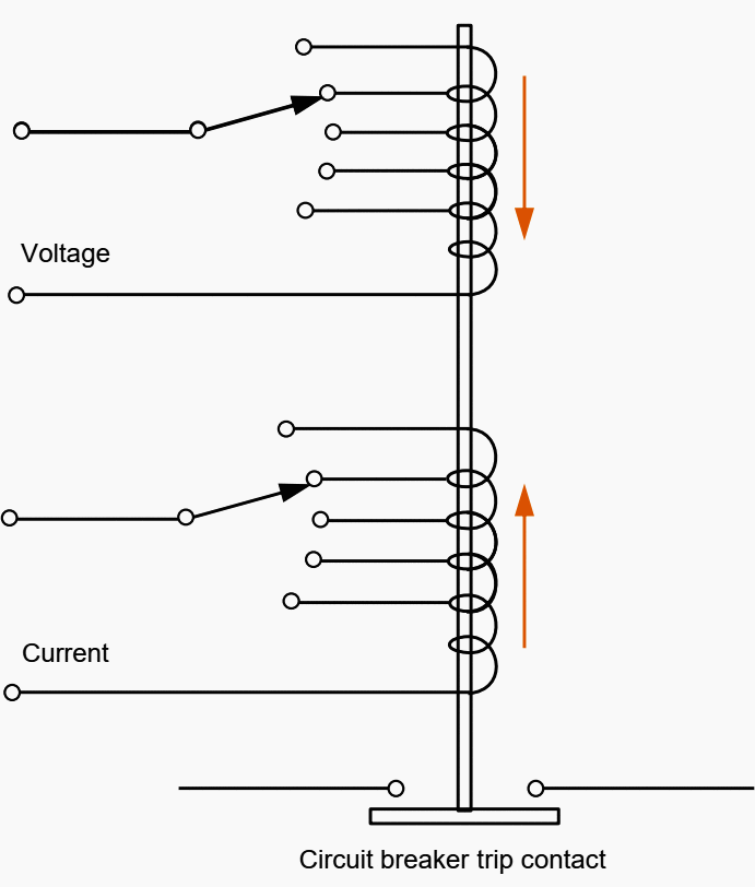
A simple element monitoring these quantities should now be considered (see Figure 3 below). The solenoid closes the trip contact. Operation is opposed by the applied voltage, occurring only when the current effect overcomes the voltage effect.
Since Ohm’s Law states: V×I=Z then the relay can be considered to have an impedance setting. It will not operate for faults involving a higher impedance, that is, for faults that are more distant.
Hence, it may be considered to operate at a distance setting called the ‘reach’ of the relay.

4. Grading
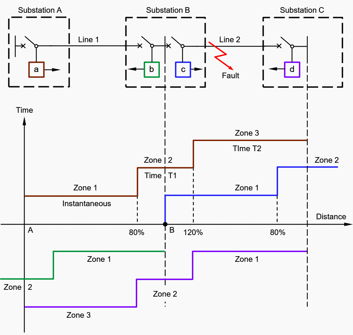
After a suitable time delay, the relay reach can be extended, enabling a second, delayed tripping zone to be covered. Further delays and extensions of reaches usually are available. Some relays are restricted to two zones, while others have five available.
Typical distance protection uses three zones. Most distance protection arrangements are set for this.
Figure 4 shows the zone/distance/time arrangement for one location only. The local voltage and current compared in a distance protection change very gradually with the location of the fault. Therefore, a precise end to the relay reach is not possible.
Note! – A blanket rule regarding settings cannot be applied. The above settings are typical only.


If several distance protections are located in series at substations on the same radial feed, the zone of adjacent relays overlaps. This provides a ‘backup’ trip, should the circuit breaker (nearest the fault) fail to trip.
In Figure 5 shown below, the fault shown between substations B and C should produce a high speed zone 1 clearance by the relay c at substation B. If the fault is not cleared, the relay at substation A will time out (typically at 0.3 seconds) and trip zone 2, providing the fault is within the zone 2 reach of the relay at A.
If the circuit is a ring, the directional feature ensures that only the protection facing (looking towards) the fault could operate the trip.

Some distance protection systems have starters which indicate the faulted phase. A separate element operates to trip the circuit breaker, indicating that the tripping element has operated.
In the series situation shown in Figure 5, all relays ‘seeing’ the fault may indicate the faulted phase or phases, even though the tripping is restricted to only one or two relays.
Other protection systems do not indicate faulted phases or zones unless they actually perform the trip function.
5. Switched Versus Full Schemes
Some distance protection arrangements have only one measuring device. The fault to be measured may be any phase to earth or phase to phase combination, hence, the particular voltage and current values to be measured need to be switched to the measuring element.
This is termed a ‘switched’ scheme.
By increasing the number of measuring elements, switching is reduced and reliability and speed are increased. If each type of fault is catered, six elements are required. When this is extended to three zones, 18 elements are required.
This arrangement is classified as a ‘full’ scheme, in contrast with the ‘switched’ scheme described earlier.
6. Measuring Elements
Figure 6 shows a simple impedance relay characteristic. The circle is the limit of the relay reach. The relay located at A operates whenever the impedance value of the line and fault place the fault within the circle.
As the operating circle is centred on the axis, it is non-directional.
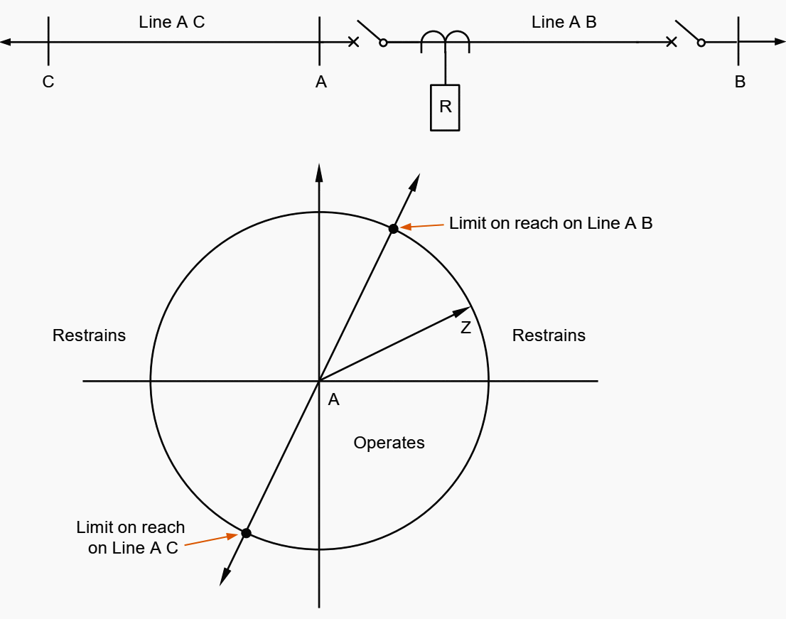

The most common form of distance protection has a Mho relay characteristic as shown in Figure 7 below. The Mho relay is inherently directional, operating only for faults in the forward direction.
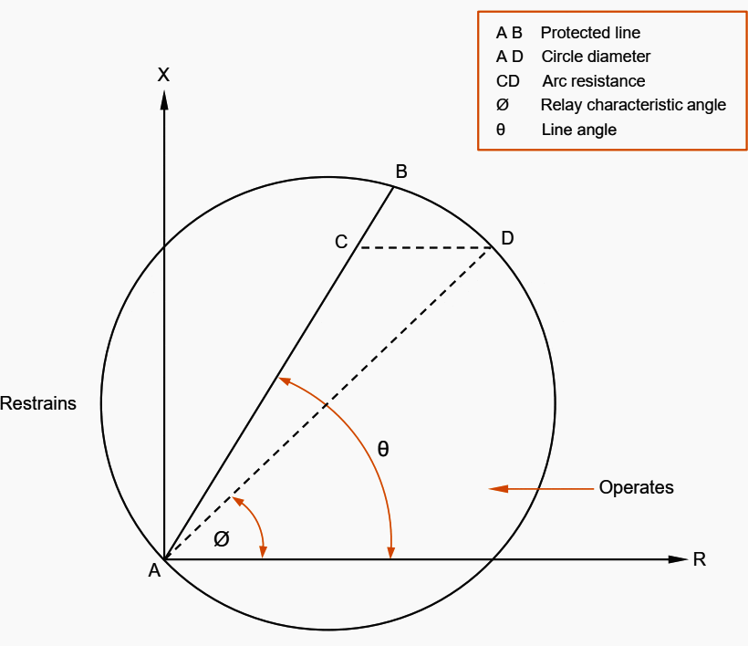

In summary, the characteristics of the impedance relay are non-directional. If used as a starting relay, it must be coupled with measuring units which incorporate the directional feature.
7. Close-On Fault
This fault is sometimes called a ‘switch on to fault’, ‘line check’ or ‘trip-on-close’. An example is where a set of earths are applied to the primary conductors of the protected line but not removed prior to energization.
Although fault current flows, a voltage will not be produced for directioning and measuring to take place. To overcome this, some protection arrangements function purely as overcurrent relays for the first 30 milliseconds (ms). to provide an instantaneous trip for ‘close-on’ faults.
8. With Communication Channel
Because of inaccuracies in relay operation, zone 1 cannot be set to cover the whole length of the line without risking loss of discrimination with other protection devices.
Figure 8 shows that only the middle 80% of the line is covered by high speed zone 1 operation at both ends of the line, the remainder being covered in zone 2 time from one end.
The protection signalling allows the distance protection to operate like a high speed unit protection, however, it takes no part in fault detection or measurement.
A description of the most frequently used forms of protection signalling follow.


8.1 Accelerated Intertripping
A fault on a line which is protected by distance protection at each end is shown in Figure 8 above. A fault F1 in the centre of the line would be cleared by both ends at high speed (approximately 5 cycles). Both protection ‘a’ and ‘b’ see the fault in zone 1.
A fault F2 near substation B, however, would be cleared as follows:
- Protection ‘a’ starts to measure and time the fault, preparatory to tripping circuit breaker a in zone 2 time.
- Protection ‘b’ would also measure the fault, high speed trip circuit breaker b in zone 1 time, and initiate a signal to intertrip protection ‘a’.
- Protection ‘a’ will receive an intertrip signal from protection ‘b’. This causes the tripping of circuit breaker a without further delay, because protection ‘a’ has already detected the fault in zone 2 (see step 1 above).
8.2 Direct Intertrip
The zone 1 relay (at the end nearest the fault) is used to send a trip signal to the remote end in order to directly trip the circuit breaker there.
In this arrangement, the relay at the receiving end is not used to confirm that there is a fault on the line, therefore, the scheme requires very secure signalling links.
8.3 Permissive Intertrip
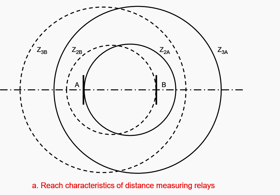
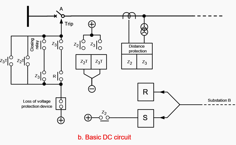
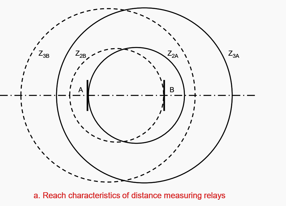
The zone 1 relay at the end closest to the fault sends a signal to the remote end of the line. However, the circuit breaker at that end is tripped only if the zone 2 or zone 3 element of the receiving relay has operated, indicating the presence of a fault on the line.
This is called an ‘underreach’ scheme, as the sending element does not ‘see’ to the end of the line. An ‘overreaching’ scheme is similar, except that it uses the zone 2 elements to send the signal (see Figure 9a and 9b).
Because fast signalling systems are used, the tripping time for both ends of the line will be only slightly different.


8.4 Blocking
The zone 2 relay (at the end furthest from the fault) is allowed to trip with only a small time delay (approximately 50 ms), unless it is blocked by a signal from the remote end (see Figure 10a and 10b).
The signal is sent by an extra, reverse element which ‘looks’ at the remote end and indicates when a fault is external to the protected line. A short time delay is needed to allow for the transmission time of the blocking signal.

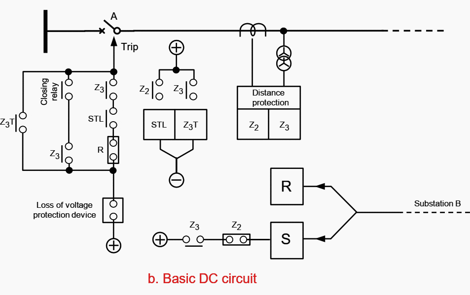

Source: Switching Operator’s Manual – Transmission Switching by Horizon Power








Very interesting topic and well explained.
Excellent explanation of Line distance protection schemes.