
Estimated Study Time: 8 minutes
Dead circuit testing methods
Dead circuit testing is testing performed with the power disconnected from the circuit. The main benefit of disconnecting power supply while tests with an external energy source are performed is to eliminate hazardous risks to the environment or the person conducting the test.
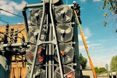
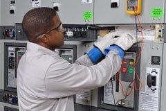
 Troubleshooting dead circuit by testing continuity with disconnected supply (photo credit: visionsensorsmag.com)
Both continuity test and insulation test can be performed in the dead circuit test. Let’s try to describe them in details:
1. Continuity test
This is to be performed on a dead circuit for checking continuity. Using an Audible Continuity Tester can do it. This tester consists of a battery as a source of energy, an audible device, and two test leads.
Figure 1 shows an example of this test with an audible continuity tester.
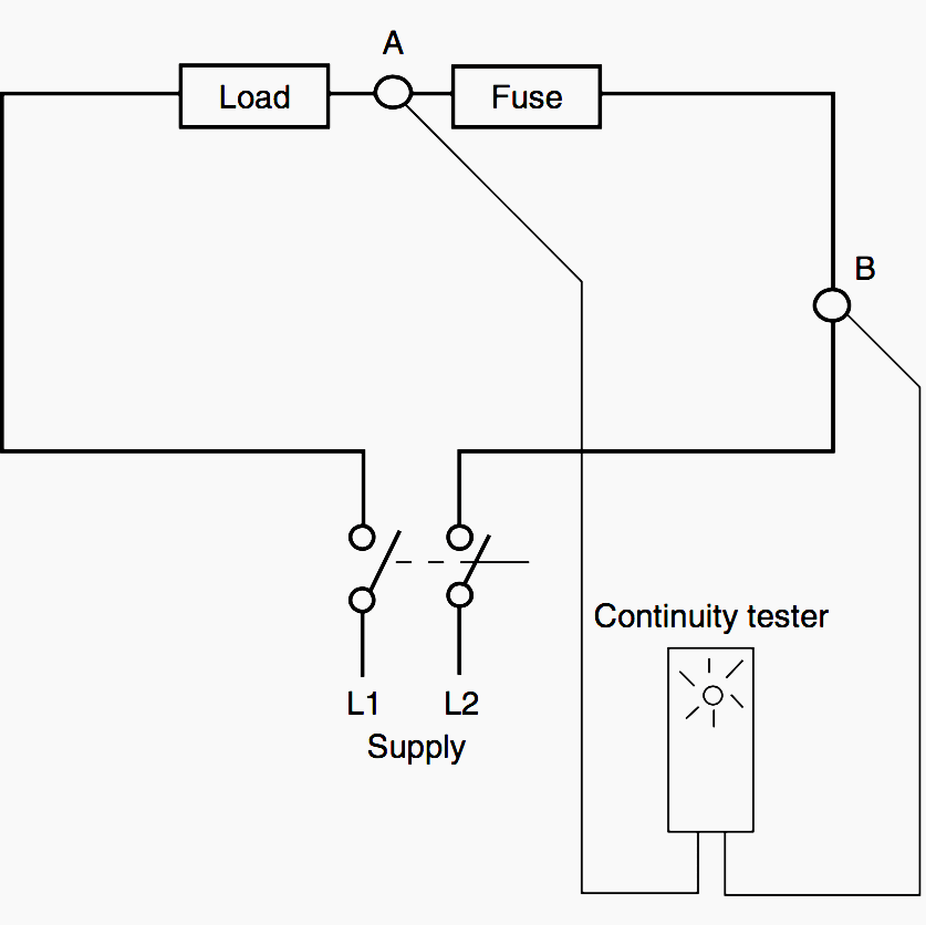
By this test, the continuity of an electrical circuit is checked to ensure that the electrical path is complete. If the path is continuous, then an audio sound is emitted to confirm path continuity and the non-existence of an open circuit. In some devices, along with the audio indication, an LED or some other visual indication is provided.
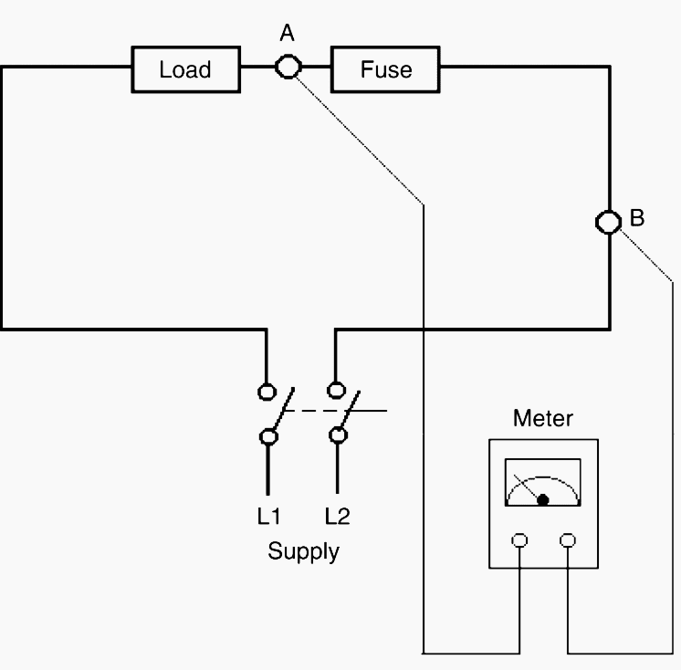
In an ohmmeter, the scale is calibrated from zero to an infinite range of resistance. When the meter shows a zero reading, it indicates that the path between two test leads has zero resistance. This, in turn, indicates that the path is a continuous one.
If the path or the conductor is open, then it will show resistance value as infinite.
In short, continuity testing is used to check the following purposes:
Integrity of cables
- Integrity of electrical circuit path
- Integrity of the earthing system (i.e., electrical continuity and low-resistance value to earth)
- Accurate wiring of a control and power circuit to the correct terminals
- Differentiate active and neutral conductors before connecting them to a device
- Check for wrong wiring interconnections between different control and power circuits. Thus indirectly, checking for short circuit paths
- Integrity of switches, fuses, and other devices
Often, a circuit where there is an open circuit fault can register excellent continuity with a low power tester or ohmmeter. But when a voltage is applied, current may not flow.
The reason for this is that the circuit may be partially continuous (Example: a partially burnt cable where one or two conductor strands may be making contact) but when feeding a heavy load it will behave as a high impedance.
This type of fault will be detected by testing on load using voltage measurements.
Go back to dead circuit testing continuity methods ↑
2. Insulation test
This is another test performed on a dead circuit only. The objective is to check for insulation of cables or a power circuit. The device used to check integrity of insulation is known as an Insulation Resistance Tester. Generally, this is used during the installation of high voltage power cables and terminations.
In Figure 3, a general motor circuit is shown with breaker, fuses, and overload relay. To check insulation of the circuit (excluding motor), disconnect the power supply by opening the breaker.
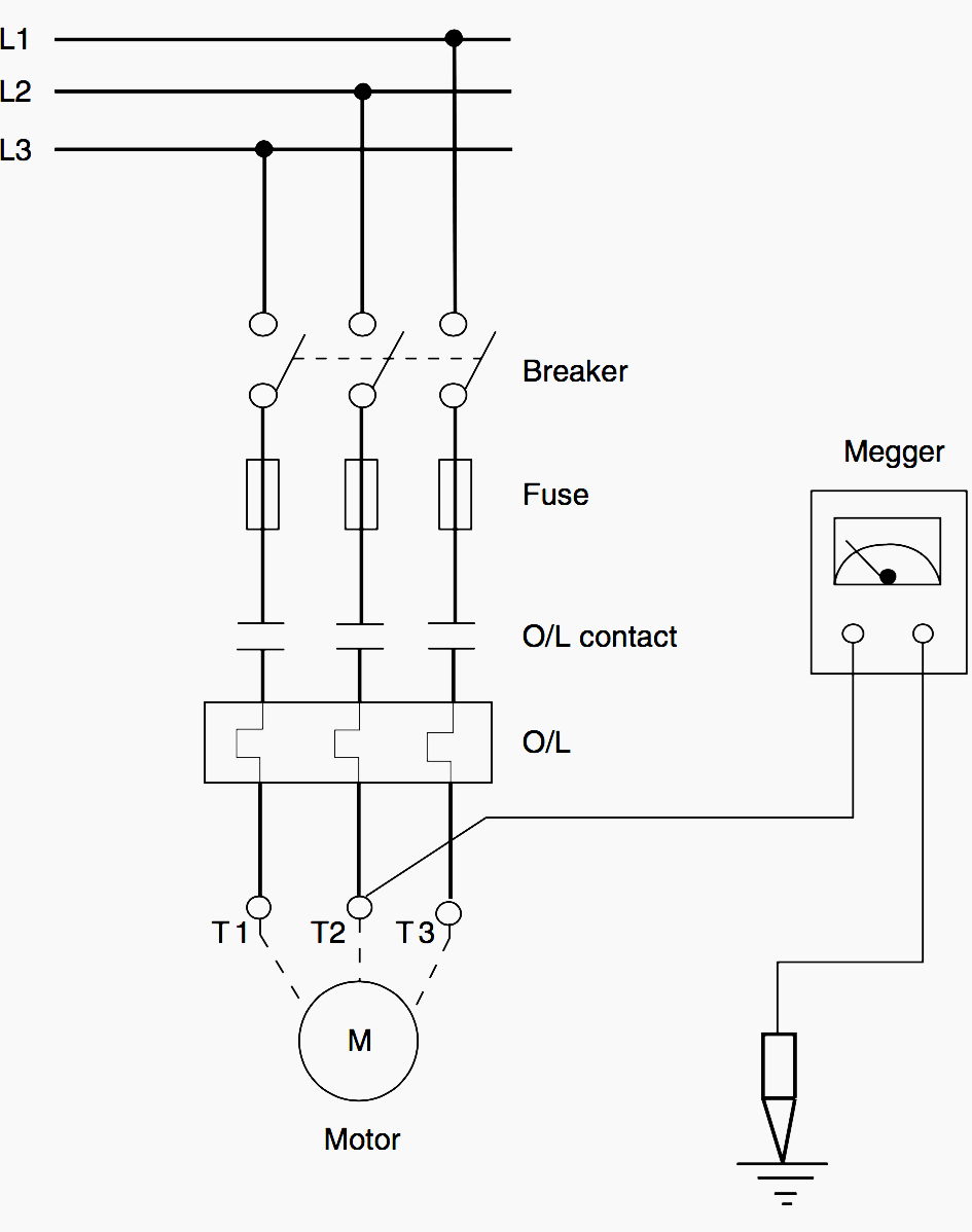
Then, isolate the motor from the circuit through terminals T1, T2, and T3. First checking insulation resistance between earth and T1, then earth and T2, and finally earth and T3 checks insulation resistances of conductors, as well as other devices.
This test is also used in fault finding, to check for earthed motors or cables and for checking insulation failure of conductors. Individual phases of three-phase motor winding can be insulation-tested only if all six leads of the winding are brought out. The winding being tested should be connected to the tester’s output with the other two windings connected together and to the earthed frame of the motor.
Where only three leads are available, the insulation of the machine winding as a whole can only be tested with reference to the earthed frame of the motor.
These insulation testers are also often incorrectly called ‘Meggers’ (by manfacturer MEGGER) and have a built-in energy source (either DC generator or battery) to produce test voltages of rating 500 V DC or more.
This is required since the electrical circuit to be tested applies voltage of different ratings.
For example, when the insulation resistance of HV cables is checked, 1000 V minimal voltage is applied, whereas for a domestic circuit 500 V is sufficient for testing.
NOTE! Testing on a live circuit requires extreme caution and should be restricted to LV circuits.
Precautions should be taken to prevent inadvertent contact of the technician with live parts. The probes and tools must be insulated with minimum exposure of conducting parts. This will minimize inadvertent bridging of two terminals which are at different potentials which can cause a short circuit and arcing leading to burn injuries to the technician.
Go back to dead circuit testing continuity methods ↑
Resource: Practical Troubleshooting of Electrical Equipment and Control Circuits – M. Brown
(Get it from Amazon)
Related electrical guides & articles


Edvard Csanyi
Hi, I'm an electrical engineer, programmer and founder of EEP - Electrical Engineering Portal. I worked twelve years at Schneider Electric in the position of technical support for low- and medium-voltage projects and the design of busbar trunking systems.I'm highly specialized in the design of LV/MV switchgear and low-voltage, high-power busbar trunking (<6300A) in substations, commercial buildings and industry facilities. I'm also a professional in AutoCAD programming.
Profile: Edvard Csanyi

This content was really helpful
I like how you mentioned that the insulation test checks the integrity of insulation cables. My brother needs to fix his power circuit and breaker at his warehouse next month. He should find a professional to do some electrical testing for his facilities.