Effects of series and shunt capacitors
At a casual look, a capacitor seems to be a pretty boring and unsophisticated device, that is, two metal plates separated by a dielectric insulating material. Couldn’t be simpler than that. The capacitor has no moving parts but instead functions by being acted upon by electric stress. But, in reality, however, a power capacitor is doing some serious work.

The capacitor is a highly technical and complex device in that very thin dielectric materials and high electric stresses are involved, coupled with highly sophisticated processing techniques.
The fundamental function of capacitors, whether they are series or shunt, installed as a single unit or as a bank, is to regulate the voltage and reactive power flows at the point where they are installed. The shunt capacitor does it by changing the power factor of the load, whereas the series capacitor does it by directly offsetting the inductive reactance of the circuit to which it is applied.
1. Series Capacitors
Series capacitors, that is, capacitors connected in series with lines, have been used to a very limited extent on distribution circuits due to being a more specialized type of apparatus with a limited range of application. Also, because of the special problems associated with each application, there is a requirement for a large amount of complex engineering investigation.
Therefore, in general, utilities are reluctant to install series capacitors, especially of small sizes.
At times, a series capacitor can even be considered as a voltage regulator that provides for a voltage boost that is proportional to the magnitude and power factor of the through current.
Therefore, a series capacitor provides for a voltage rise that increases automatically and instantaneously as the load grows. Also, a series capacitor produces more net voltage rise than a shunt capacitor at lower power factors, which creates more voltage drop. However, a series capacitor betters the system power factor much less than a shunt capacitor and has little effect on the source current.
Figure 1 – Voltage phasor diagrams for a feeder circuit of lagging power factor: (a) and (c) without and (b) and (d) with series capacitors


Consider the feeder circuit and its voltage phasor diagram as shown in Figures 1a and 1c. The voltage drop through the feeder can be expressed approximately as:
VD = IR cosθ + IXL sinθ (Equation 1)
where:
- R is the resistance of the feeder circuit
- XL is the inductive reactance of the feeder circuit
- cosθ is the receiving-end power factor
- sinθ is the sine of the receiving-end power factor angle
However, when a series capacitor is applied, as shown in Figures 1b and 1d, the resultant lower voltage drop can be calculated as:
VD = IR cosθ + I (XL − XC) sinθ (Equation 2)
where Xc is the capacitive reactance of the series capacitor.
Go back to the Contents Table ↑
1.1 Overcompensation Problem
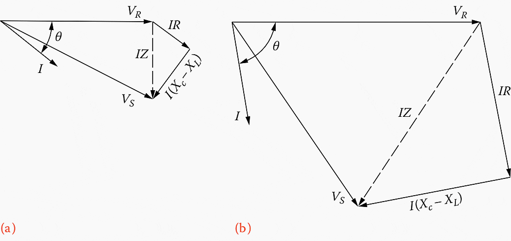
Usually, the series-capacitor size is selected for a distribution feeder application in such a way that the resultant capacitive reactance is smaller than the inductive reactance of the feeder circuit. However, in certain applications (where the resistance of the feeder circuit is larger than its inductive reactance), the reverse might be preferred so that the resultant voltage drop is:
VD = IR cosθ − I (XC – XL) sinθ
The resultant condition is known as overcompensation.
This is especially harmful to lights (shortening their lives) and causes light flickers, resulting in consumers’ complaints.
Figure 2 – Overcompensation of the receiving-end voltage: (a) at normal load and (b) at the start of a large motor

Go back to the Contents Table ↑
1.2 Leading Power Factor
To decrease the voltage drop considerably between the sending and receiving ends by the application of a series capacitor, the load current must have a lagging power factor. As an example, Figure 3a shows a voltage phasor diagram with a leading-load power factor without having series capacitors in the line.
Figure 3b shows the resultant voltage phasor diagram with the same leading-load power factor but this time with series capacitors in the line. As can be seen from the figure, the receiving end voltage is reduced as a result of having series capacitors.
Figure 3 – Voltage phasor diagram with leading power factor: (a) without series capacitors and (b) with series capacitors


When cosθ = 1.0, sinθ ≅ 0, and therefore,
I (XL − XC) sinθ ≅ 0(Equation 3)
Hence, Equation 2: VD = IR cosθ + I (XL − XC) sinθ becomes VD ≅ IR
Thus, in such applications, series capacitors practically have no value. Because of the aforementioned reasons and others (e.g., ferroresonance in transformers, subsynchronous resonance during motor starting, shunting of motors during normal operation, and difficulty in protection of capacitors from system fault current), series capacitors do not have large applications in distribution systems.
However, they are employed in sub-transmission systems to modify the load division between parallel lines.
They are also employed in subtransmission systems to decrease voltage regulation.
Suggested reading – The mystery of nuisance tripping incidents in transformer protection
The mystery of nuisance tripping incidents in transformer protection that worry engineers
Go back to the Contents Table ↑
2. Shunt Capacitors
Shunt capacitors, that is, capacitors connected in parallel with lines, are used extensively in distribution systems. Shunt capacitors supply the type of reactive power or current to counteract the out-of-phase component of current required by an inductive load.
In a sense, shunt capacitors modify the characteristic of an inductive load by drawing a leading current that counteracts some or all of the lagging component of the inductive load current at the point of installation.
However, shunt capacitors do not affect current or power factor beyond their point of application. Figures 4a and 4c show the single-line diagram of a line and its voltage phasor diagram before the addition of the shunt capacitor, and Figures 4b and 4d show them after the addition.
Figure 4 – Voltage phasor diagrams for a feeder circuit of lagging power factor: (a) and (c) without and (b) and (d) with shunt capacitors


Voltage drop in feeders, or in short transmission lines, with lagging power factor can be approximated as:
VD = IRR + IXXL(Equation 4)
where:
- R is the total resistance of the feeder circuit, Ω
- XL is the total inductive reactance of the feeder circuit, Ω
- IR is the real power (in-phase) component of the current, A
- IX is the reactive (out-of-phase) component of the current lagging the voltage by 90°, A
Go back to the Contents Table ↑
2.1 Example
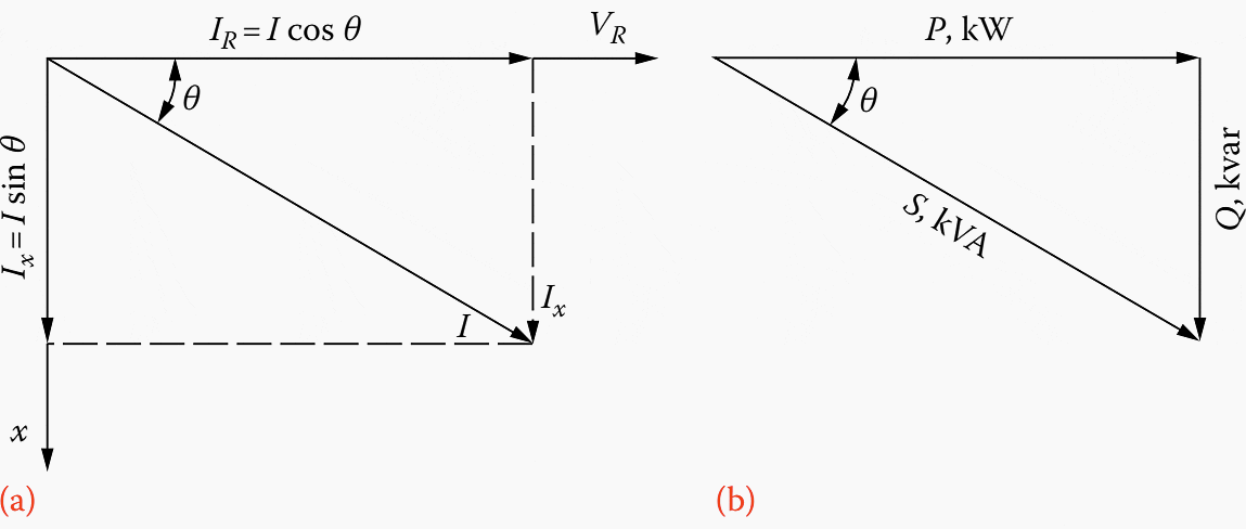
Consider the right-angle triangle shown in Figure 5b. Determine the power factor of the load on a 460 V three-phase system, if the ammeter reads 100 A and the wattmeter reads 70 kW.
Figure 5 – (a) Phasor diagram and (b) power triangle for a typical distribution load

Solution
- S = √3 (V)(I) / 1000
- S = √3 (460 V)(100 A) / 1000
- S ≅ 79.67 KVA
Thus,
- PF = cosθ = P / S
- PF = 70 KW / 79.67 KVA
- PF ≅ 0.88 or 88%
When a capacitor is installed at the receiving end of the line, as shown in Figure 4b, the resultant voltage drop can be calculated approximately as:
VD = IRR + IXXL − ICXL(Equation 5)
where IC is the reactive (out-of-phase) component of current leading the voltage by 90°, A.
The difference between the voltage drops calculated by using Equations 4 and 5 is the voltage rise due to the installation of the capacitor and can be expressed as VR = ICXL
Go back to the Contents Table ↑
3. Power Factor Correction
A typical utility system would have a reactive load at 80% power factor during the summer months. Therefore, in typical distribution loads, the current lags the voltage, as shown in Figure 5a. The cosine of the angle between current and sending voltage is known as the power factor of the circuit.
If the in-phase and out-of-phase components of the current I are multiplied by the receiving-end voltage VR, the resultant relationship can be shown on a triangle known as the power triangle, as shown in Figure 5b. Figure 5b shows the triangular relationship that exists between kilowatts, kilovoltamperes, and kilovars.
Note that, by adding the capacitors, the reactive power component Q of the apparent power S of the load can be reduced or totally suppressed.
Figure 6 – Illustration of (a) the use of a power triangle for power factor correction by employing capacitive reactive power and (b) the required increase in the apparent and reactive powers as a function of the load power factor, holding the real power of the load constant.
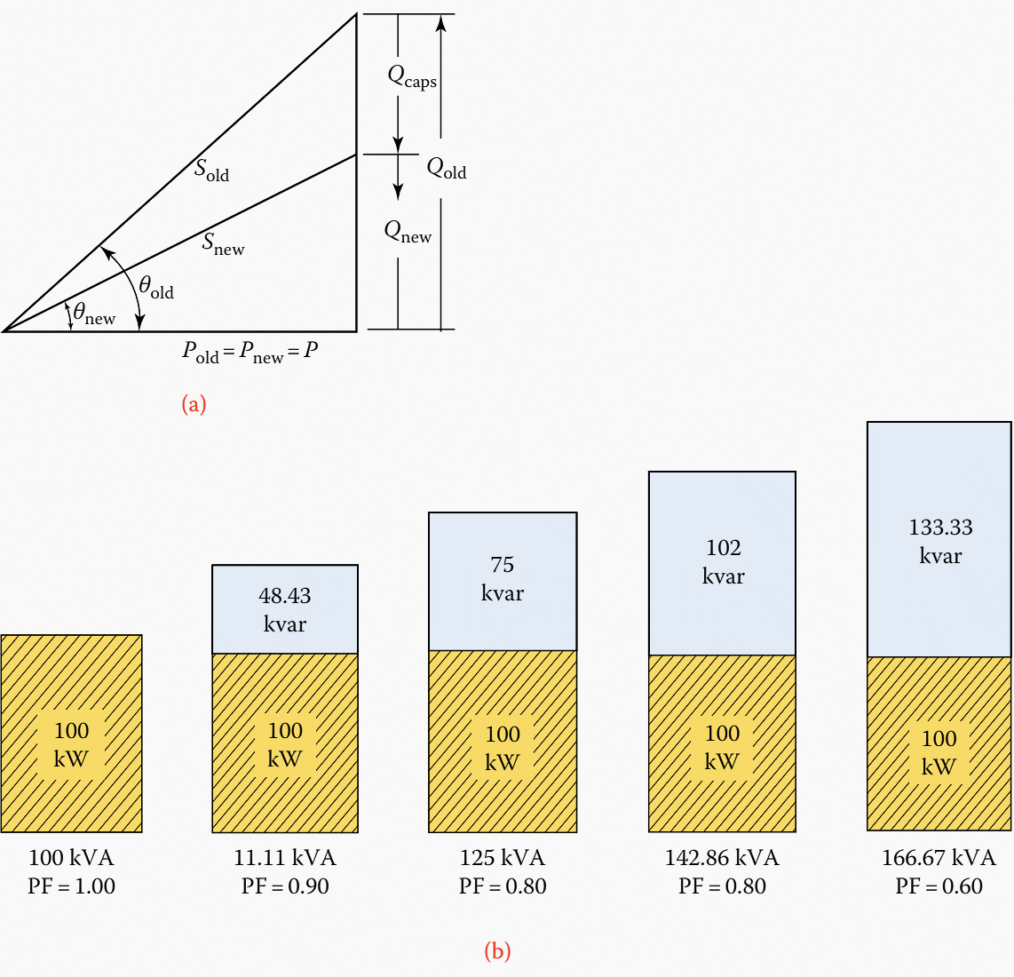

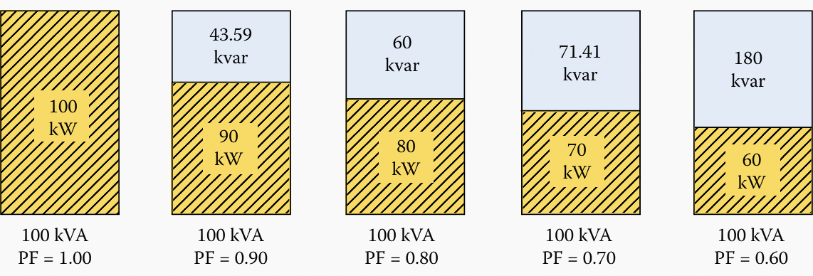
Figures 6a and 7 illustrate how the reactive power component Q increases with each 10% change of power factor. Figure 6a also illustrates how a portion of lagging reactive power Qold is canceled by the leading reactive power of capacitor Qc.
Note that, as illustrated in Figure 6, even an 80% power factor of the reactive power (kilovar) size is quite large, causing a 25% increase in the total apparent power (kilovoltamperes) of the line. At this power factor, 75 kvar of capacitors is needed to cancel out the 75 kvar of the lagging component.
Figure 7 – Illustration of the change in the real and reactive powers as a function of the load power factor, holding the apparent power of the load constant.

As previously mentioned, the generation of reactive power at a power plant and its supply to a load located at a far distance is not economically feasible, but it can easily be provided by capacitors (or overexcited synchronous motors) located at the load centers.
Figure 8 illustrates the power factor correction for a given system.
Figure 8 – Illustration of power factor correction


As illustrated in the figure, capacitors draw leading reactive power from the source; that is, they supply lagging reactive power to the load. Assume that a load is supplied with a real power P, lagging reactive power Q1, and apparent power S1 at a lagging power factor of:
- cosθ1 = P / S1, or
- cosθ1 = P / (P2 + Q12)1/2
When a shunt capacitor of Qc kVA is installed at the load, the power factor can be improved from cosθ1 to cosθ2, where:
- cosθ2 = P / S2
- cosθ2 = P / (P2 + Q22)1/2 or
- cosθ2 = P / [P2 + (Q1 − QC)2]1/2
Go back to the Contents Table ↑
3.1 The Concept of Leading & Lagging Power Factors
Many consider that the terms “lagging” and “leading” power factor are somewhat confusing, and they are meaningless if the directions of the flows of real and reactive powers are not known. In general, for a given load, the power factor is lagging if the load withdraws reactive power; on the other hand, it is leading if the load supplies reactive power.
This is shown in Figure 9 and indicated in Table 1.
Figure 9 – Examples of some of the sources of leading and lagging reactive power at the load
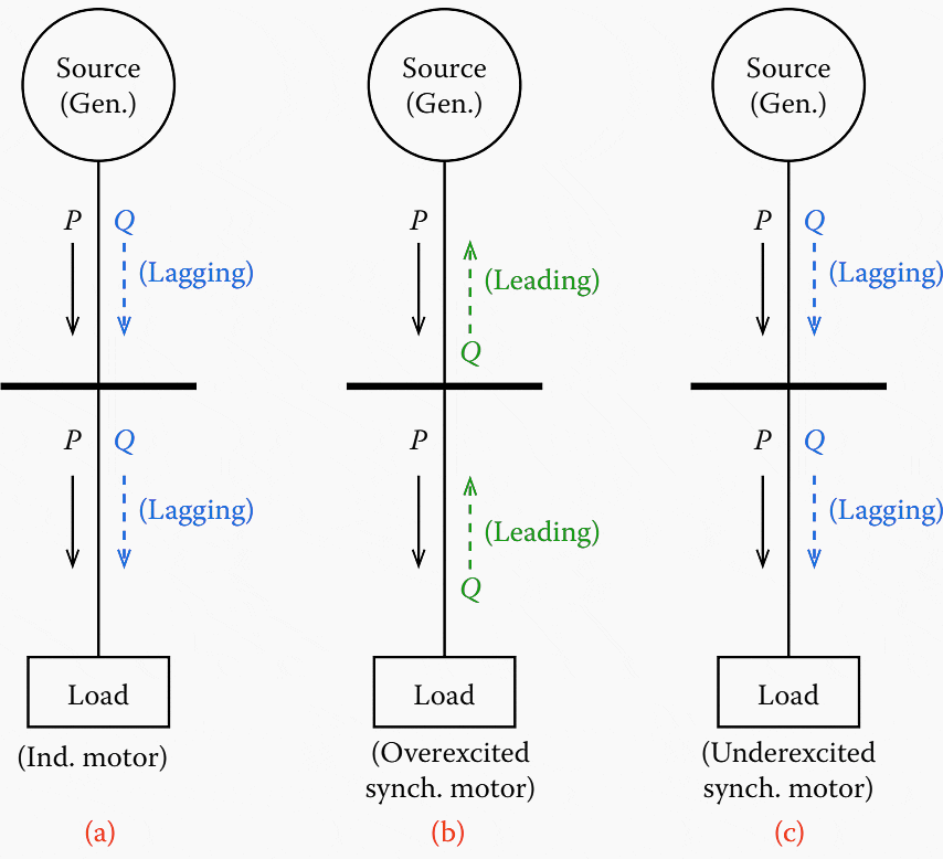

On the other hand, an underexcited synchronous motor withdraws both the real and reactive power from the source, as indicated. The use of varmeters instead of power factor meters avoids the confusion about the terms “lagging” and “leading.”
Such a varmeter has a zero center point with scales on either side, one of them labeled “in” and the other one “out”.
Table 1 – Power Factor of load and source
| Load Type | At Load | At Generator | ||||
| P | Q | Power Factor | P | Q | Power Factor | |
| Induction Motor | In | Out | Lagging | – | – | – |
| Induction generator | – | – | – | Out | Out | Lagging |
| Synchronous motor (Underexcited) | In | In | Lagging | Out | Out | Lagging |
| Synchronous motor (Overexcited) | In | Out | Leading | Out | In | Leading |
Go back to the Contents Table ↑
3.2 Economic Power Factor
As can be observed from Figure 8b, the apparent power and the reactive power are decreased from S1 to S2 kVA and from Q1 to Q2 kvar (by providing a reactive power of Q), respectively. The reduction of reactive current results in a reduced total current, which in turn causes less power losses.
Thus, the power factor correction produces economic savings in capital expenditures and fuel expenses through a release of kilovoltamperage capacity and reduction of power losses in all the apparatus between the point of installation of the capacitors and the power plant source, including distribution lines, substation transformers, and transmission lines.
However, as the corrected power factor moves nearer to unity, the effectiveness of capacitors in improving the power factor, decreasing the line kilovoltamperes transmitted, increasing the load capacity, or reducing line copper losses by decreasing the line current sharply decreases.
Therefore, the correction of the power factor to unity becomes more expensive with regard to the marginal cost of capacitors installed.
Further Studying – How to avoid common mistakes during wiring and startup of power factor correction (PFC) cubicle
How to avoid common mistakes during wiring and startup of power factor correction (PFC) cubicle
Go back to the Contents Table ↑
Source: Electric Power Distribution Engineering Guide by Turan Gönen






Hi Edvard!
Thanks for sharing your knowledge, I don’t understand why professors struggled so much explaning the difference between series and shunt capacitors. Your article just clear my thoughts!
How can i join this programs
Good job
very useful information. please correct the value in figure 6b from 11.11kVA to 111.11kVA and pf from 0.8 to 0.7 in respected images. Thanks
Excellent article!!! Very easy to understand in simple terms.
In figure 6b the result 111.11 KVA; SQRT(P^2+Q^2)
Kind regards!!!
I have dealt with Power Capacitors during my tenure at Saudi Elec Cos. Central Region, Riyadh. In later days Static Thyristor controlled Variable Reactive Power capacitors projects were added. Many will like to get treatise on that.
Good article sir i read your article always
Good article sir i read your article always, Thanks to share with us
Once again a very good article Edvard..
Thanks, keep up the good work.
Sincerely,
Madhav (+917757971133)
Thank you, Madhav.
I am an electrician by trade and I am currently teaching Electrical for certificate levels in Papua New Guinea, South West Pacific. Just by going through the information on your website has opened up my mind to a deeper and broader dimension of Electrical Engineering of which I am very interested and I would like to have an Electrical Engineering qualification.
i am the most happiest person in the worpd for having you and the platform.
im based in south africa and im will to know how can we work together and make business with all the information you have.
my whatsapp no. +27743119363
thanks
Thank you, Robert.