Differential protection (87R/∆I)
Differential protection is the most commonly applied protection function for bus-connected oil-immersed shunt reactors. The function offers instantaneous protection for internal phase to phase and phase to ground faults. Internal in this context means faults located in the area between the CTs on either side of the reactor.
The differential protection may be of the low impedance or high impedance type. Let’s dive into the details of each protection type and its applications.
- Low-impedance phase differential protection
- High-impedance phase differential protection
- Application notes:
1. Low-impedance phase differential protection
The sum of currents to a node must, according to Kirchhoff’s current law, be zero. The differential protection utilizes this fact and is based on a comparison of the currents on all sides of the protected object. The sum of currents flowing into an object such as a shunt reactor is zero except when there is a fault in the object (or within the zone limited by the current transformers).
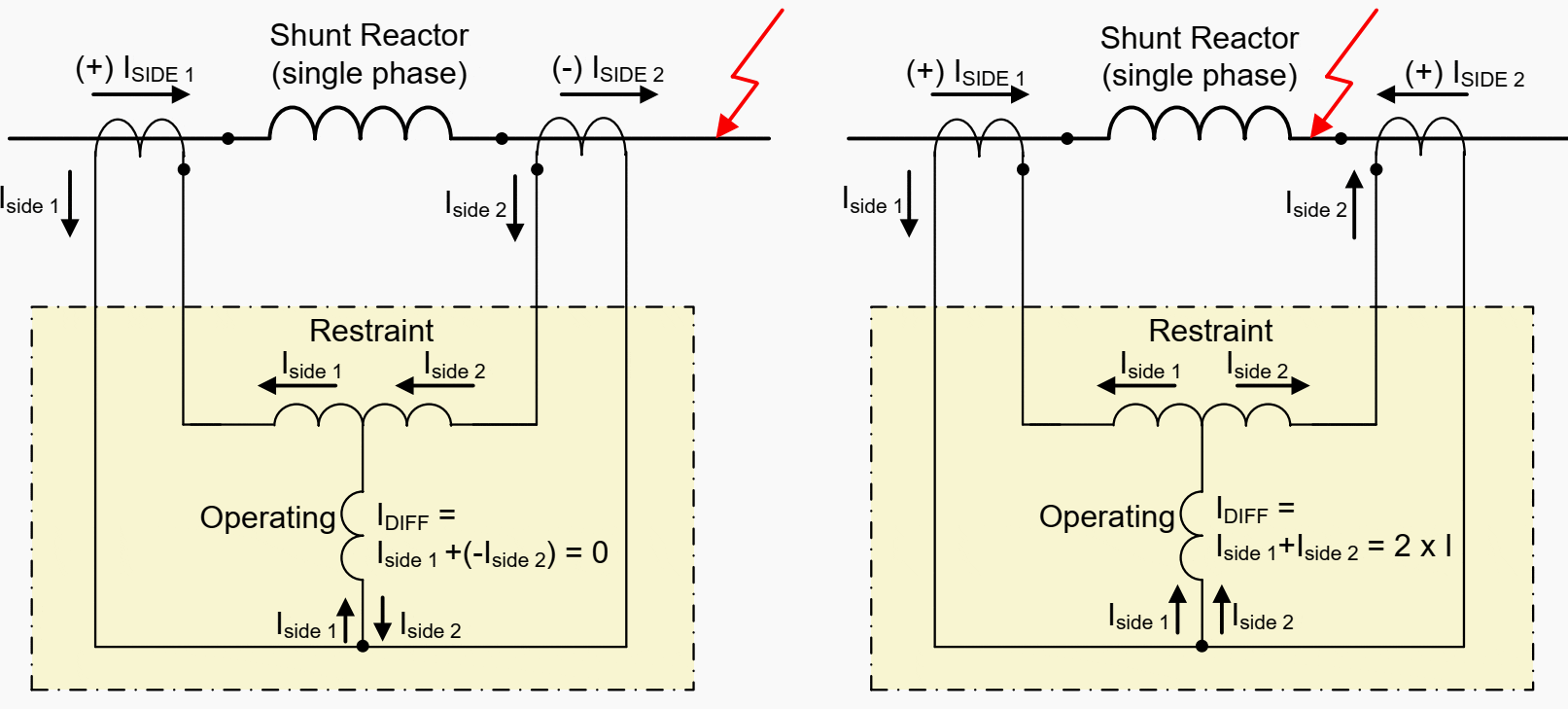
The principle of current summation is illustrated in Figure 1 below. Please note that primary currents flowing in the direction towards the object are regarded as positive.
Under certain operating conditions the CT’s secondary current may not represent exactly the current flow on the primary side. Under these conditions, Kirchhoff’s current law is not satisfied and may lead to false differential currents.
Figure 1 – Principle of low impedance phase differential protection

In order to not operate inadvertently under such conditions, simple differential protection purely based on measurement of the differential current would have to be set less sensitive.
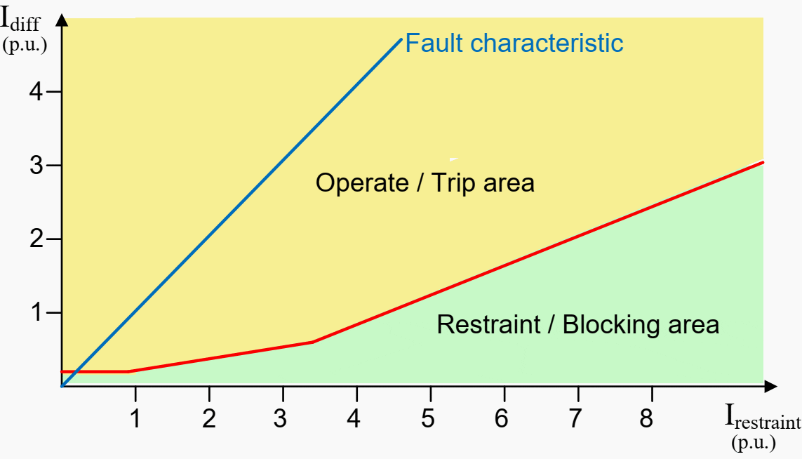
As indicated in Figure 2 below, the restraint and differential currents may be measured via dedicated measuring inputs. This is true for electromechanical and solid-state relays. The name restraint current comes from the electromechanical relay design, where this current produced a restraint torque on the moving disc, while the differential current produced the operating torque.
In numerical low-impedance differential protections, the differential and restraint quantities are calculated from the measured phase currents.
Figure 2 – Tripping characteristic: Example

The relay manufacturers are forming the restraint quantity in various ways. Some of the variants are:
- IRestraint = Iside1 − Iside2 (see Figure 1 above)
- IRestraint = |Iside1| + |Iside2|
- IRestraint = (|Iside1| + |Iside2|)/ 2
- IRestraint = MAX |Ix|, where Ix is the highest phase current
In the first case (mainly used in analog protections for two-terminal objects) the resulting restraint current will be zero for internal faults and twice the through flowing current for external fault. In most of the other variants where the absolute values of the phase currents are used as a restraint, an internal fault is expected to follow approximately the fault characteristic shown in Figure 2 above.
Common for all variants is that an external fault with large magnitude currents flowing through the protected object the resulting diff and restraint quantity should be a point along the restraint axis. At the same time, the protection under such conditions requires a larger differential current to reach the tripping area and thus allowing a certain amount of CT error.
There is no uniform term for the quantity used to stabilize the differential protection. The following terms are often used:
- Stabilizing current (Istab)
- Bias current (Ibias)
- Restraint current (Irestr.)
Internal faults with high magnitude fault currents may possibly result in heavy CT saturation and thereby produce false 2nd harmonic content in the differential current. In the worst case, this might lead to an undesired blocking of the restrained differential function.
Numerical differential protection using 2nd harmonic blocking is therefore normally also equipped with an additional high-level unrestrained diff function. The purpose of this function is to offer secure and fast tripping for such internal faults with high magnitude fault currents.
Suggested course – Transformer Differential Protection Course: Understanding Schematics, Relay Settings and Testing
Transformer Differential Protection Course: Understanding Schematics, Relay Settings and Testing
Go back to the Contents Table ↑
2. High-impedance phase differential protection
High impedance differential protection is also in widespread use as differential protection on shunt reactors. This is another variant of the current comparison principle. The functional principle is that the relay, as the name indicates, are of a high ohmic type and responds to the resulting voltage across the differential junction points.
With reference to Figure 3 below, the principle is as follows:
For external faults, the voltage across the differential junction point will be approximately zero. For internal faults the differential currents will result in a significant voltage increase over the junction points and the relay will operate. The relay itself is a quite simple and robust construction and operates at high speed when a set voltage or current level is exceeded.
Figure 3 – Principle of high impedance phase differential protection
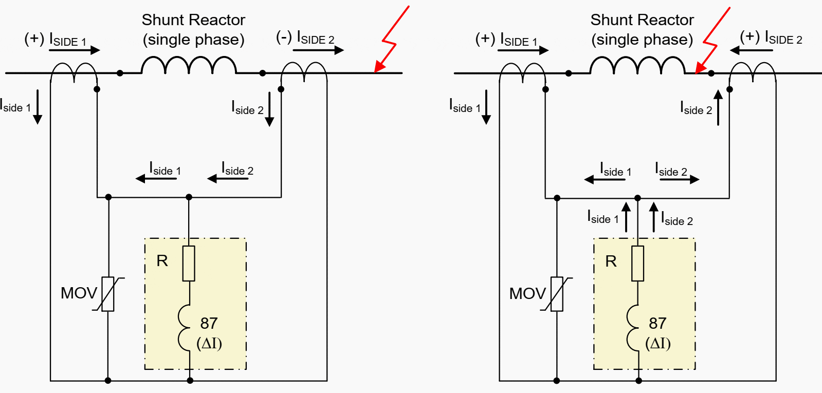

A voltage-dependent resistor (varistor) is normally added to the circuit in order to protect the differential relay from damaging high voltage levels during internal faults.
The high impedance differential relays are generally regarded as stable against in adverted operation during external faults. This is due to the fact that the relay impedance is much higher than the impedance of a saturated CT. As illustrated in Figure 4 below the false differential current caused by a saturated CT causes the false differential current to mainly circulate through the secondary of the saturated CT and the relays operating level should not be exceeded.
It is also obvious that if a CT is short-circuited, this will not be detected by the relay and lead to a permanent blocking of the function.
Figure 4 – High impedance differential protection – stabilizing principle


Go back to the Contents Table ↑
3. Application notes
Applied to an oil-immersed shunt reactor with directly grounded neutral the differential protection offers fast detection and tripping in case of internal phase to phase or phase to ground faults. Most of the possible fault localization in the winding are expected to be covered by this protection function.
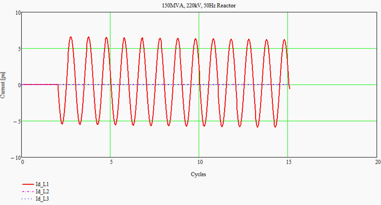
Simulation results have shown that even the currents during a winding to ground fault 1% from the neutral could be easily detected by the differential protection (i.e. provided adequate protection sensitivity). See Figure 5 below.
However, internal winding turn-to-turn faults will not be detected by differential protection.
Figure 5 – Differential currents of a 1% turn to ground fault in phase L1 at the neutral point of a 150 MVA, 220 kV, 50Hz shunt reactor

Generally, the type of differential protections devices used for shunt reactors is the same as for used for power transformers. Compared to power transformers the application on shunt reactors is a lot easier.
- No need for vector group correction
- No need for zero-sequence current elimination
- The inrush currents are measured on both sides and should theoretically not be seen by the protection as a differential current.
- The magnitude of the through fault currents during external faults are relatively small (i.e. during external ground fault approximately 1.0 p.u.).
There is however some possible challenges related to phase differential protections on shunt reactors that must be addressed.
Go back to the Contents Table ↑
3.1 Switching in conditions
When energizing an iron core shunt reactor the actual peak value of the current might rise to a value between 3 and 5.5 times rated current. The inrush currents in the three phases will experience a different degree of DC offset. Due to the long DC-Time constant of the shunt reactor, the time to the steady-state condition may be fairly long and in the order of seconds.
Under such conditions, the operating point of the magnetic flux in the CT’s will increase in the same direction as the DC component. This situation persists as long as there is a DC component in the primary current. A result of this may be a time-delayed saturation of the current transformer.
Specifically for low impedance differential protection connected to closed-core CT’s, this time delayed saturation may cause undesirable protection operation. The fundamental value of the primary currents may in this situation be close to the rated current of the reactor.
The differential protection then operates in the sensitive part of the tripping characteristic. Even a small differential current may in this situation lead to an incorrect trip by the differential protection.
Some utilities always use CT’s of the same make and with identical ratings on both sides of the shunt reactors. The philosophy is to avoid uneven saturation and thus prevent significant values of false differential currents. This is not a 100% fail-safe practice, but reports indicate that it has been quite successfully applied to shunt reactors.
One important reason for this is the fact that in shunt reactor applications the CT’s on the terminal- and neutral-side both suffer under the same conditions.
Other measures to avoid unwanted tripping of low impedance differential protection under these conditions might be:
- Use of 2nd harmonic blocking/restraint feature in combination with cross blocking functionality
- Use of adaptive DC-biasing
Additional security against undesired operations may be achieved by activating the so-called “cross blocking function”. This function blocks the differential function in all phases for a limited time as long as the 2nd harmonic threshold is exceeded in one of the individual reactor phases.
As these settings increase the possibility for an unwanted blocking during real internal fault conditions, it is advisable to use it in combination with the unrestrained differential stage which is available in most numerical low impedance differential protection.
In modern protection applications, the introductions of adaptive DC-biasing offer a desirable operational feature that enhances security by stabilizing the differential protection under such conditions.
Suggested courses – Relay Control and Protection Bundle: Complete Relay Circuitry and Schematics (Five Courses)
Learn the essentials of relay protection and control in power systems. This includes a complete relay circuitry and a deep understanding of all control and protection aspects. Special attention is paid to reading and analyzing schematics of transformer differential and distance protection. This bundle includes five courses in a total duration of 33 hours 47 mins.
Relay Control and Protection Bundle: Complete Relay Circuitry and Schematics (Five Courses)
Go back to the Contents Table ↑
3.2 CT ratio versus the level of short circuit current
Generally, for shunt reactor installations low CT ratios are often selected due to its low operating current during normal operating conditions. The reactors are however often connected to busbars or lines with very high fault levels. As a result, the magnitude of the currents during internal reactor faults may reach such high levels that the CT cores suffer severe saturation.
For low impedance differential protections, the resulting distorted differential currents may contain a large degree of 2nd harmonic current and thus cause a blocking of the restrained differential function. Selecting a higher CT ratio may improve the situation in some instances.
Generally, it also has quite low requirements for CT dimensioning. Dependable protection operation should in most cases be guaranteed as long as the CT’s steady-state saturation current exceeds the protection setting level. The actual protection CT requirements must nevertheless be checked against the relay manufacturer’s recommendations.
Figure 6 – Example of tripping characteristic for a two-stage numerical low-impedance differential protection applied to a shunt reactor
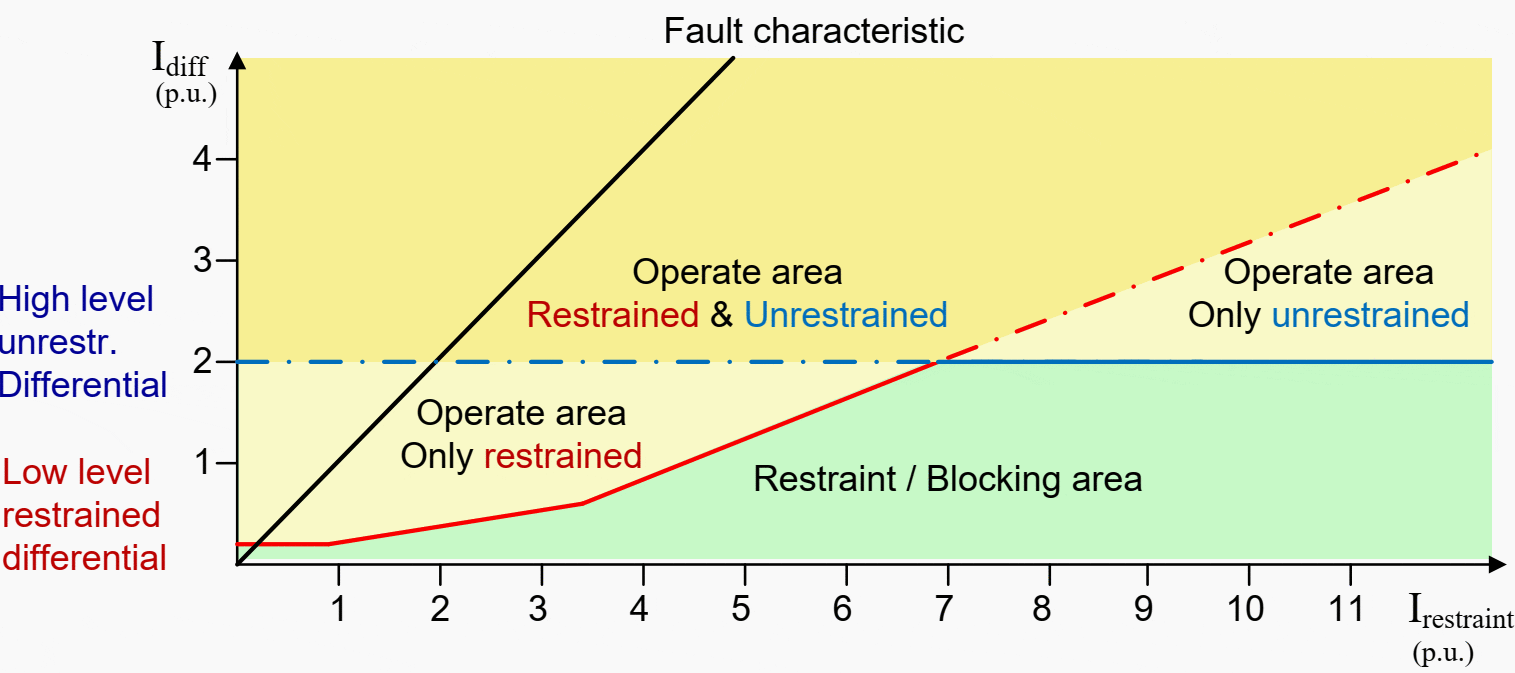

For a shunt reactor application, it should be possible to choose a setting of the high-level unrestrained diff function as low as 200% of the rated reactor current.
This relatively sensitive setting is possible due to the fact that:
- There will be no high level through fault currents for external faults.
- The possible false differential currents caused by temporary CT saturation during inrush conditions will be decisive for the setting. These inrush currents are of relatively moderate level.
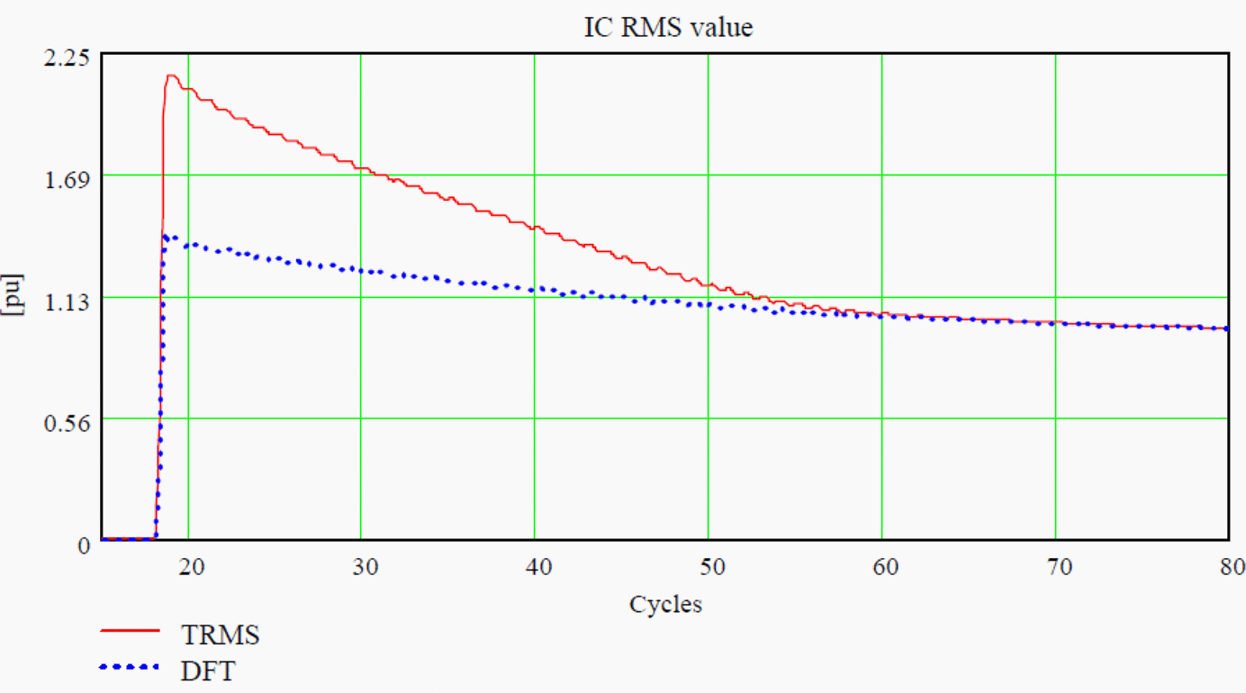
- The numerical differential protection normally utilizes the DFT (Discrete Fourier Transform) filter technique of the input current which effectively suppresses the dc component.
Figure 7 – Shunt reactors inrush current in phase C with fully DC offset – response of two different types of digital filters

Go back to the Contents Table ↑
Source: Protection, Monitoring and Control of Shunt Reactors by Working Group B5.37, Cigre


33/11.5 kV Mobile SS 31.5 MVA
very good thanks
The contents to be in pdf format which is downloadable