Open-circuit and short-circuit test
Open circuit test and short circuit tests are performed on a transformer to determine equivalent circuit, voltage regulation and efficiency of transformer. The power required for these tests on transformer is equal to the power loss occurring in the transformer.

Open Circuit Test on Transformer
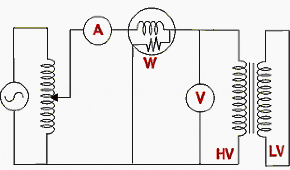
The connection diagram for open circuit test on transformer is shown in the Figure 1. A voltmeter, wattmeter, and an ammeter are connected in LV side of the transformer as shown.
The voltage at rated frequency is applied to that LV side with the help of a variac of variable ratio auto transformer. The HV side of the transformer is kept open. Now with help of variac applied voltage is slowly increase until the voltmeter gives reading equal to the rated voltage of the LV side.
As no load current Ie is quite small compared to rated current of the transformer, the voltage drops due to this current then can be taken as negligible. Voltmeter reading V1 can be considered equal to secondary induced voltage of the transformer.
The input power during test is indicated by wattmeter reading. As the transformer is open circuited, there is no output hence the input power here consists of core losses and copper loss in during no load condition.

But, the no load current in the transformer is quite small compared to full load current so copper loss due to the small no load current can be neglected. Hence the wattmeter reading can be taken as equal to core losses in transformer.
Let us consider wattmeter reading is Po.
Po = V12 / Rm
Where:
- Rm is shunt branch resistance of transformer
- If, Zm is shunt branch impedance of transformer
Then, Zm = V1 / Ie. Therefore, if shunt branch reactance of transformer is Xm. Then, (1 / Xm)2 = (1 / Zm)2 – (1 / Rm)2
Therefore it is seen that the open circuit test on transformer is used to determine core losses in transformer and parameters of shunt branch of the equivalent circuit of transformer.
Short Circuit Test on Transformer
The connection diagram for short circuit test on transformer is shown in the Figure 2. A voltmeter, wattmeter, and an ammeter are connected in HV side of the transformer as shown.
The voltage at rated frequency is applied to that HV side with the help of a variac of variable ratio auto transformer.

The LV side of the transformer is short circuited. Now with help of variac applied voltage is slowly increase until the ammeter gives reading equal to the rated current of the HV side. After reaching at rated current of HV side, all three instruments reading (voltmeter, ammeter and wattmeter readings) are recorded.
The ammeter reading gives the primary equivalent of full load current IL.
As the voltage, applied for full load current in short circuit test on transformer, is quite small compared to rated primary voltage of the transformer, the core losses in transformer can be taken as negligible here.
| Title: | The basics of power transformer (theory, operation, testing and protection) – Engr. Adeel Zafar |
| Format: | |
| Size: | 881 KB |
| Pages: | 48 |
| Download: | Here 🔗 (Get Premium Membership) | Video Courses | Download Updates |


If there a discount if I enrol as enterprice membership. I am a retired electrical contractor.
Name : Johnny Lim
email: newtdeng@singnet.com.sg
Excellent!
This is very usefull for me
Sir,
Really, it’s very informative and practical.
Thanks
The Articles are very informative and practical