Voltage Drop and the NEC
The following are National Electrical Code (NEC) references with regard to maximum voltage drop: branch circuits NEC 210.19(A)(1), feeders NEC 215.2(A)(4), sensitive Electronic Equipment NEC 647.4(D) and other considerations.

Branch Circuits
NEC 210.19(A)(1) Informational Note No. 4 limits the voltage drop at the furthest outlet of a load to 3% of the applied voltage. This allows 2% drop in the feeder.
Alternatively, the maximum combined voltage drops on the feeder and branch circuits going to the furthest outlet of a load should be limited to 5%.
For example, if a panel board is located adjacent to the transformer feeding it, one might assert that there is nominally 0% voltage drop in the short feeder from the transformer secondary to the adjacent panel board, thus leaving the full 5% voltage drop for use on the branch circuits powered from that panel board.
Feeders
NEC 215.2(A)(4) Informational Note No. 2 also limits the voltage drop at the furthest outlet of a load to 3% of the applied voltage. This allows 2% drop in the feeder.
Alternatively, the maximum combined voltage drops on the feeder and branch circuits going to the furthest outlet of a load should be limited to 5%. This is the same requirement stated above for branch circuits.

Sensitive Electronic Equipment
NEC 647.4(D) covers the use of separately-derived 120 V, single-phase, three-wire systems with 60 V between each of the two hot conductors and the neutral, similar to the 120/240V service to our houses, but at half the voltage.
Alternatively, the maximum combined voltage drops on the feeder and branch circuits going to sensitive electronic equipment should be limited to 2.5%. These values are half of the values given for feeders and branch circuits.
These special electrical systems typically used for sensitive audio/video or similar types of electronic equipment and are only allowed in commercial or industrial occupancies and are not discussed further in this course.
Other Considerations
A 3% voltage drop on a single-phase, 120 VAC system would be 0.03×120V = 3.6 V. Similarly, a 2% voltage drop on a three-phase, 480 VAC system would be 0.02×480V = 9.6V.
The main concern of voltage drop calculations is to make sure the load has enough voltage to function properly.
NEC 90.5(C) states that explanatory information provided in the Code, such as Informational Notes, are not enforceable as Code requirements, so voltage drop recommendations that appear as Informational Notes in the Code are not enforceable. They are usually required and expected, however, on most projects, for conductor run lengths that merit consideration: Consider the Rule-of-Thumb below.
It is important to note that the voltage drop requirement for Sensitive Electronic Equipment in NEC 647.4(D) is a code-enforceable requirement, not an Informational Note.
Rule-of-Thumb
A common rule-of-thumb that many people use to determine whether or not a voltage drop calculation is required is to compare the one-way cable length in feet to the applied voltage.
If the one-way cable length in feet is almost or more than the value of the applied voltage, then a voltage drop calculation should probably be considered.
| Title: | Voltage drop calculations (formulas, phasor diagram and real-world examples) – David A. Snyder, PE |
| Format: | |
| Size: | 1.8 MB |
| Pages: | 57 |
| Download: | Here 🔗 (Get Premium Membership) | Video Courses | Download Updates |


Excellent.!!
A correction:
NEC 215.2(A)(4) Informational Note No. 2: (error)
NEC 215.2(A)(1)(b) Informational Note No. 2: NEC 2020, pages 74 y 75.
Greetings
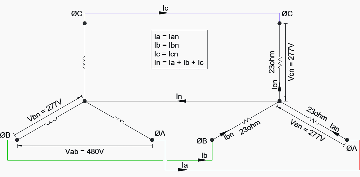
in the diagram, it shows unbalanced source , why?
The posts are very educative.
It’s very good and refreshing. I am a retired electrical engineer.
Great arrivals and posts. I look forward to them everday!
Good refreshing of basics. Thanks for many such articles