
Battery Energy Storage Systems
An energy storage system is the ability of a system to store energy using the likes of electro-chemical solutions. Solar and wind energy are the top projects the world is embarking on as they can meet future energy requirements, but because they are weather-dependent it is necessary to store the energy generated from these sources.

Energy storage systems absorb the excessive energy when generation exceeds predicted levels and supply it back to the grid when generation levels fall short. Electric Storage technologies can be utilized for storing excess power, meeting peak power demands and enhance the efficiency of the country’s power system.
These technologies include electrochemical, water electrolysis, compressed air, flywheels and superconducting magnetic energy storage.
A battery energy storage system is of three main parts; batteries, inverter-based power conversion system (PCS) and a Control unit called battery management system (BMS). Figure 1 below presents the block diagram structure of BESS.
Figure 1 – Main Structure a battery energy storage system

Battery systems are made of different types of rechargeable secondary batteries; batteries that can be charged. The following sub-sections discuss the main features of various types of batteries.
1. Lead Acid
These are the oldest and evolved batteries. They consist of a sponge metallic lead anode, a lead-dioxide cathode and a sulfuric acid solution electrolyte. They have numerous favourable traits such as relatively affordable, simplicity of manufacturing thereof, and acceptable life cycle under measured conditions, with a major drawback of using a heavy metal component that makes them harmful to the environment.
Due to the high cost associated with them, the limited life-span and low energy density, these batteries are not advantageous for the large-scale applications.
2. Sodium Sulphur (NaS)
They are regarded as the most advanced high-temperature batteries, even though they are relatively new in power system applications. Made of active materials of molten sodium and molten Sulphur, separated by a solid beta alumina ceramic electrolyte. They are favourable to use in relatively large-scale BESS applications; Due to their inexpensive materials, exceptional high energy density, high-efficiency charge/discharge rate, zero maintenance, and long-life specifications.
The system must constantly be monitored, to prevent the reaction with the atmosphere, because the interaction of pure sodium with air will result in a disastrous explosion instantly.
3.Lithium- ion (Li-ion)
These batteries are composed from lithium metal or lithium compounds as an anode. They comprise of advantageous traits such as being lightweight, safety, abundancy and affordable material of the negatively charged electrode “cathode” making them an exciting technology to explore. Li-ion batteries offer higher charge densities and have a minimum environmental impact as the lithium oxides can be recycled.
They can provide the much-needed power by the network instantaneously due to the response time that’s in the order of milliseconds.
Although various BESS technologies exist with relevant benefits, Li-Ion BESS are more promising for large scale application. Therefore, lithium-ion BESS will be considered for this dissertation
Control methods to charge/discharge BESS
The BESS is operational in two modes; the discharging mode to alleviate the utility when the distribution network is down or during the peak-load period time and charging mode to fill the battery bank during an off-peak period or when the network gets restored.
Possible ways to discharge the BESS, with the assumption the batteries are fully charged are:
- Time based control with constant discharge rate
- Time-Temperature based control with stable discharge
- Time-Temperature Control with variable discharge
- Power or Voltage control
- Radio-Control (part of SCADA system)
The PCS with the help of BMS can supply back-up power with a low distortion AC voltage to the distribution loads via the point of common interconnection via a breaker.

The main Control features of PCSs to consider are:
1. Active/Reactive power control
The PCSs provide both active and reactive power control functions. When the active/reactive command value exceeds the rated value, active power output takes priority over reactive power. PCS controls the charge/discharge flow of the battery bank as required according to the active/reactive power command from the remote SCADA system.
2. Grid Interaction features
Grid regulations for distribution systems have critical requirements on control functions of PCS, such as low voltage ride-through (LVRT), and the control functions are stored in the control circuit of PCS.
The auto-restart function is one of those included in the control circuit, to ensure that the PCS can disconnect from the grid automatically when a grid fault is detected, and also enable for the PCS to restart and reconnect to the grid automatically when the fault is cleared.
3. Stand-alone operation
When the grid fails, the PCS can switch to stand-alone operation to supply the network loads independently, and when the grid recovers the PCS can switch back to normal operation mode to charge/discharge.
The PCS provides the rated AC voltage at the rated frequency to load.
Optimal placement of BESS
BESS can be placed at different locations on the power system network to ensure continuity of supply for all customers under any abnormal conditions, the potential locations are; the high voltage side of the substation, Secondary side of the substation or at the secondary side of the mini-substation and act as a residential community focused system.
1. BESS at primary substation
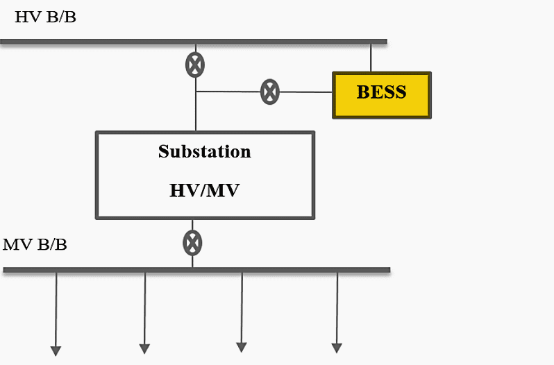
Battery energy storage system may be connected to the high voltage busbar(s) or the high voltage feeders with voltage ranges of 132kV-44 kV; for the reliability of supply, substations upgrades deferral and/or large-scale back-up power supply.
Figure 3 depicts a block diagram showing an example of how the BESS can be integrated into the distribution system via the High voltage busbar.
Figure 3 – Integrating BESS via the HV busbar block diagram
2. BESS at secondary substation
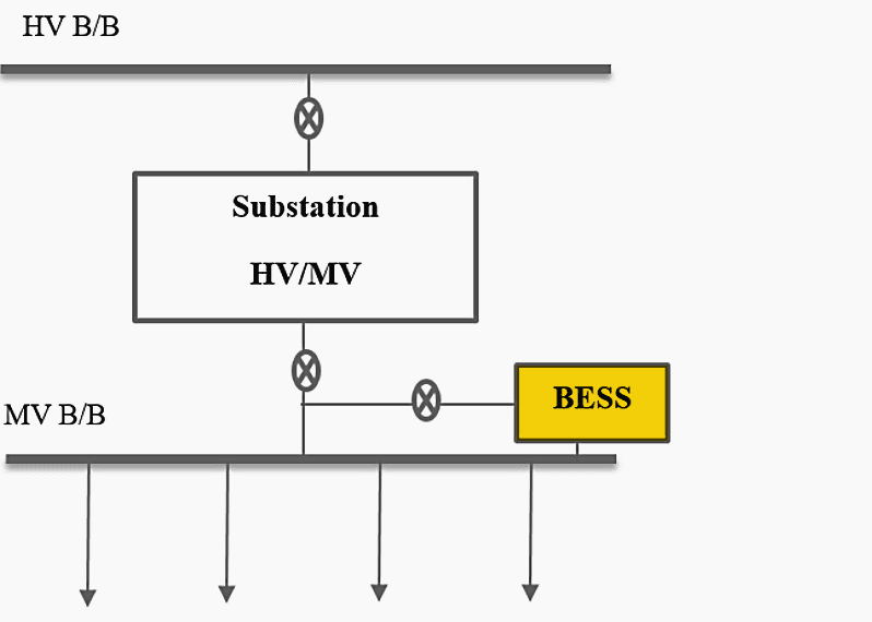
Battery Energy storage system may be connected to the medium voltage busbar(s) or to the medium voltage feeders with voltage ranges of 33kV-1kV; for peak-shifting, substation upgrades deferral, additional capacity, or medium-scale back-up-supply.
Figure 4 depicts a block diagram showing an example of how the BESS can be integrated into the distribution system via the medium-voltage busbar.
Figure 4 – Integrating BESS via the MV busbar block diagram
3. BESS at the loads
The BESS may further be connected as close as possible to the loads, by either being placed by the mini-substations (MV/LV TRFR) or at the customer’s point of connection 400V-230V for residential loads and at the medium voltage feeders with voltage ranges of 33kV-11 kV (depending on the voltage the customer requires) for industrial loads. For voltage support, frequency stabilization, solar smoothing for networks with PV systems, or back-up-supply.
Figure 5 depicts a block diagram showing an example of how the BESS can be integrated into the distribution system directly to the loads.
Figure 5 – Integration of BESS directly to the loads block diagram

From the above block diagrams of possible BESS placement, the diagrams shown in figures 10 and 11 are the best fit with regard to the objective of reducing outages in substations and continuously supplying customers, as they offer voltage support, additional capacity and backup-supply. Therefore, both block diagrams will be implemented and simulated using MATLAB/Simulink.
Simulink the preliminary and main research to be presented in next chapters, 4 and 5.
| Title: | Reducing power substation outages by using battery energy storage systems (BESS) – by Disebo Cornelia Sesing; A dissertation submitted in partial fulfillment of the requirements for the degree of Master of Science in Electrical Engineering, College of Agriculture, Engineering and Science, University of KwaZulu Natal |
| Format: | |
| Size: | 3.3 MB |
| Pages: | 77 |
| Download: | Here 🔗 (Get Premium Membership) | Video Courses | Download Updates |


I am an Electrical engineer and working facility manager . Looking for the power back up system like Solar/Wind power based UPS/Inverter with backup time for about 48 hours for 600 kVA load