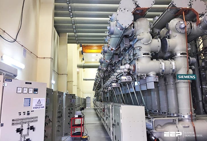
GIS operating principles
GIS is totally capsuled, that is impervious to and distinguished from the external ambiance. This is a huge benefit from environment viewpoint such as ocean based oil rigs, particle or mist pollution sources. Nevertheless, because the gas isolated switchgear is totally capsuled, a needed visible disconnecting means cannot be directly accomplished.

The grounding and disconnect switches, needed in both air and gas insulated arrangements, will have view ports in gas isolated devices.
GIS has a reduced “footprint” than a corresponding air insulated substation, usually less than half the area. Even though a gas isolated substation will initially cost more than a similar air insulated substation, the economics may rationalize its installation where land is pricey, such as city centres.
GIS may also be rationalized when a low profile substation is required to “hide” a substation.
GIS operation
As a gas isolated switchgear element is isolated for servicing, it will be required to affirm the places of the grounding and disconnect switches. Since these switches are totally cased within the aluminum enclosure, it is essential for producers to allow for view ports.
The view ports allow, by visual verification, to check the position of the different disconnect and grounding switches. In some situations, this can be completed with using just a flashlight.
In other situations, at strange access points, a camera with a light source supplied by the producer is handy.
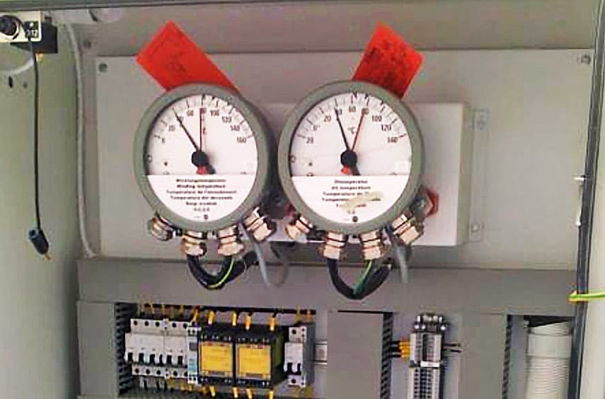
The protective relays related with the GIS devices may or may not put in the same place. Since SF6 gas behaves as a vital insulator, it is required to keep adequate density within the GIS devices. Hence, there will be alarm and trip contacts from sensors for each gas separation to warn staff or isolate devices when the insulation integrity is insufficient.

One of the advantages of GIS devices over its air insulated equipment is the minimal servicing that is needed of the GIS. This is mainly due to the breakup of the conductors and isolators from the outside ambience. Modern GIS devices have very low SF6 gas leakage rates.
The operation counter may help in finding out if any servicing will be needed on the mechanisms, but this is generally many years between maintenance.
Safety concerns
Staff safety holds a crucial priority status when servicing a GIS. The metallic enclosure of the high voltage spaces are grounded where direct contact is not possible, except at the external links. This safety element is underlying in the GIS arrangement.
Moving elements such as operation rods or motor drives are typically protected with protective plates or showed by colouring for greater safety. In case of an internal fault, pressure relief elements open the enclosing to free the hot gas to the surrounding internal elements.
These pressure relief elements are made to guide the gas stream away from staff to save them and ensure their safety.
To set up GIS inside indoor or outdoor substation safety regulations are further described in IEC 61936-1. Installation regulations are presented to integrate factory assembled and type-tested GIS equipment.
Demands of grounding, accessibility, fire protection, safety of walkways and other areas are described.
| Title: | The basics of Gas Insulated Substation (GIS) for students – Velimir Lackovic, Char. Eng. at Continuing Education and Development, Inc. |
| Format: | |
| Size: | 377 KB |
| Pages: | 36 |
| Download: | Right here | Video Courses | Membership | Download Updates |


Store Layout Design for material GIS
Want to know the formula to find creepage distance for electrical conductor for 132 kv line.
Dear Sir,
I am an electrical engineer,having 11 years of experience in Testing and Commissioning of power projects.Presently working as a protection inspector at Qatar.
If you know any openings for electrical engineer,Kindly contact me.