
Insulation coordination study
Over time there has been a significant rise in demand and transferring such a huge amount of power from generating stations to distribution substations via 765kV transmission lines have comparatively more losses (I2R losses) than if the voltage is higher. This gives rise to Ultra High Voltage (UHV) systems. UHV systems deal with voltages up to 1200kV.
China has been constructing a 1000kV UHV system and has been facing many technical issues and it has been increasing prominently. For any electrical system, insulation coordination and overvoltage protection are the most critical issues to be addressed.
Insulation Coordination is a designing criterion for any electrical equipment which enables the design of insulation for the equipment in such a way that it minimizes interruptions during steady-state conditions and also minimizes damages in case of transient overvoltages and this is done economically.
Protection devices eliminate surges or reduce their effect.
Before constructing an actual transmission system for any system, data regarding the topological area is taken, these data are useful to predict faults in the foreseeable future and to design the system accordingly.
EHV/UHV systems and insulation coordination
Ultra-high voltage (UHV) systems are created to satisfy large power transmission requirements and hence becomes important to reduce transients over the system which could lead to system failure. Similar to Extra high voltage (EHV) a number of factors affect the insulation strength.
However, in UHV the time to crest in switching overvoltage can be higher than 250 μs.
The methodology while implementing insulation coordination is to determine the stresses and assess the strength of the system on the basis of quantitative analysis or a perceived degree of reliability. So for this process, all sources of stress that can be applied to the system is considered and the minimum insulation strength should be greater than the applied stress under all circumstances.
To be able to perform a productive insulation coordination study, the outcome of the study will be a selection of specifications of electrical strengths of all equipment, the phase to ground, phase to phase clearances and the leakage or creepage distance of external porcelain.
According to need surge arrester must also be selected.
The transmission and distribution circuits which connect a substation, load centres, act as a telephone line picking up surges and delivering them to the opposite end. This is especially true when it comes to lightning overvoltages. If these surges have higher voltages than what the equipment can withstand then these surges should be prevented from reaching the equipment or at least must be mitigated to acceptable values of faults that the system can withstand.
Of the various overvoltages that occur in any system as mentioned below, insulation coordination should withstand all of them and if there are cases where the system fails to withstand the overvoltage then protective devices must be implemented in those cases to bring the overvoltage range within the required limits.
Overvoltages in Ultra High Voltage Systems
Types of overvoltages in the UHV system according to their duration.
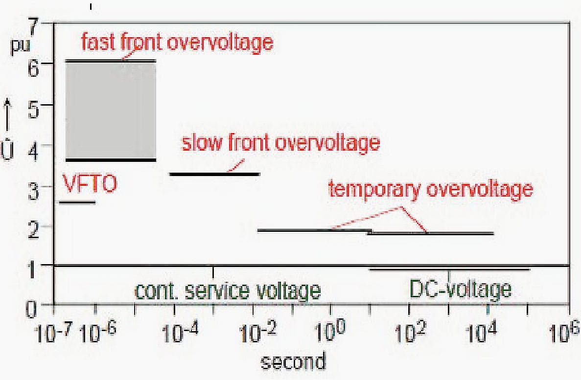
1. Temporary Overvoltage
Mainly arises due to single-phase earth faults on the lines except on which the fault occurs. Temporary overvoltages increase the stress on internal insulation and are present for a duration of around 1 second. Further temporary voltages can also occur due to resonance and ferroresonance while energizing and deenergizing transformers.
Load rejection overvoltages caused in Ultra High Voltage (UHV) usually are severe compared to extra-high voltage (EHV) due to lengthier transmission lines higher capacity. Shunt reactors, temporary overvoltage protection relays are used to mitigate the effects of temporary overvoltages.
2. Slow Front Overvoltage Analysis
Mainly due to earth faults on the faulty line. The consequence could be loss of 3 lines due to failure in one phase. The magnitude of such overvoltage can reach up to 1.5 p.u.
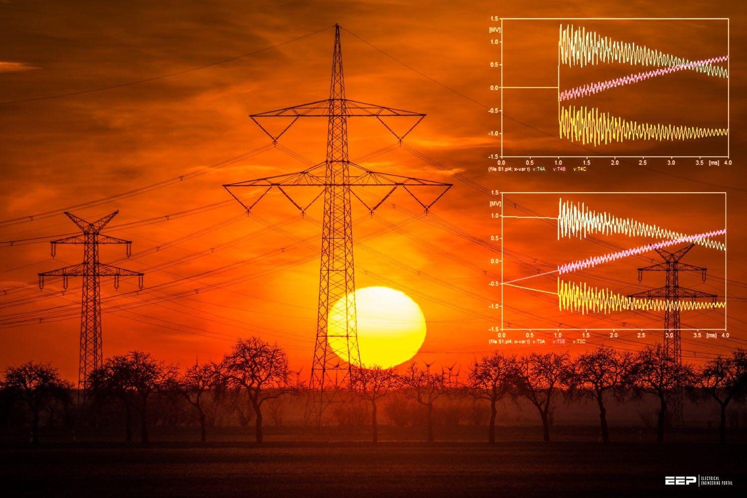
3. Fast Front Overvoltages
Mainly due to lightning on overhead lines and disconnector switching in substations. Disconnector switching in substations can have overvoltage as high as 7 p.u. Protective devices are needed in such cases to reduce the voltage as the nominal voltage itself is as high as 1200 kV.
This is the main focus of this paper as fast front overvoltages provide maximum stress on the system.
4. Very Fast Front Overvoltage
Mainly due to disconnector switching operation and line to enclosure breaks down in SF6 gas-insulated substations. Overvoltages up to 2 p.u. can occur due to these faults.
Various protection devices such as Surge Arresters, Pre-Insertion Resistors/Inductors, Synchronous Close/Open Control, Surge Capacitors are among the few equipment that can be used to mitigate overvoltages in UHV.
| Title: | Insulation coordination study for an ultra-high voltage (UHV) AC transmission system – Dr. Bruce Mork, Harshil Patel, and Ravi Raj Gupta at Michigan Technological University |
| Format: | |
| Size: | 2.1 MB |
| Pages: | 38 |
| Download: | Right here | Video Courses | Membership | Download Updates |

Excellent Topic
THIS IS VERY GOOD INFORMATION FOR ME BEING A ELECTICAL ENGINEER IN j&k STATE WE ARE DEALING UPTO 220KV LINES AND SUBSTATIONS.
THANKS AND REGARDS
How can this be applied in Nigeria
Insulation of material that repels the electric and magnetic field of flowing current