Interconnected ring main network
Due to low voltage on the distribution side of the power system, high currents and power losses are experienced. The pressure on utilities to improve the overall efficiency in the power system has forced them to concentrate on reducing the power loss on the distribution level, since it contributes most power losses in the power system.

Researchers have discussed and developed different algorithms to solve the power loss reduction problem in distribution networks. However, these methods were developed for radial network operations. However, most large urban distribution networks are operated as ring networks.
Furthermore, although ring main networks are believed to have less power losses compared to radial networks, loss of an important component in a ring main network can cause an increase in power losses leading to power shortage in the network. To improve the state of a network is the task of optimal load flow studies.
This thesis focuses on developing an efficiency plan that can be used by network operators in response to a failure of a major component such as a substation infeed or a primary U/G cable. The developed efficiency plan is using the capacitor addition and network reconfiguration techniques to give the optimal configuration for power loss reduction.
Development of the efficiency plan work flow diagram
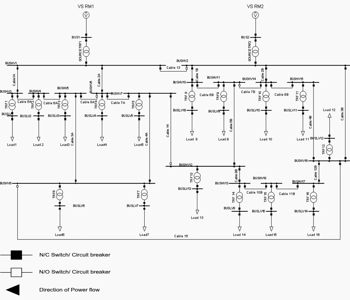
Figure 1 shows the one-line diagram of the large urban interconnected ring main distribution network that was used to evaluate and develop the efficiency plan (methodology).
Such a network is typical in industry and consists of multiple ring main networks.

The network shows two interconnected ring main networks namely Ring main Network 1 (RM1) and Ring main Network 2 (RM2). Both ring main networks, RM1 and RM2, have a voltage source of 66∠0° kV and a frequency of 50 Hz. The two networks are interconnected via U/G Cables 13, 14 and 15.
RM1 has a step down transformer rated at 7 MVA, 66/11 kV with two primary U/G Cables, 1A and 2A. U/G Cables, 3A, 4A, 5A, 6A, 7A and 8A complete the ring main system of RM1.
RM2 has a source step down transformer rated at 10 MVA, 66/11kV with three primary U/G Cables 1B, 2B and 3B and secondary U/G Cables 4B, 5B, 6B, 7B, 8B, 9B, 10B, 11B and 12B. The load ratings, transformer ratings and U/G cable ratings for both networks are shown in Tables A.1, A.2 and A.3, in Appendix A.
The studies will mainly be focused on the RM1 network. The RM2 network will however be considered in the case of network configuration when extra power is needed at RM1.

Efficiency plan Methodology
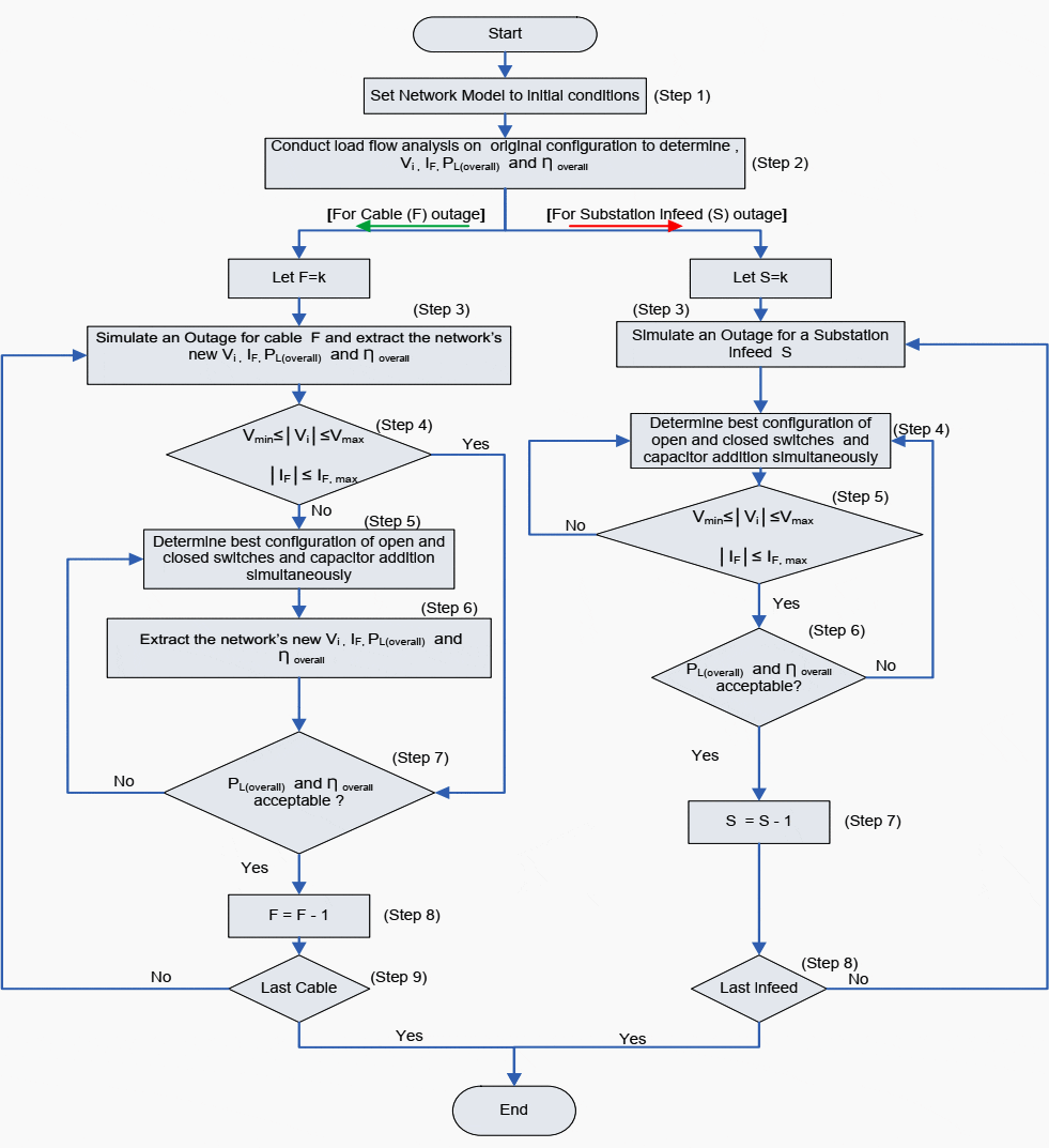
Figure 2 shows an efficiency plan work-flow diagram. The work-flow diagram depicts an empirical approach for finding the optimal configuration that will minimise the power losses in a ring main network that is under a contingency condition, while satisfying the given constraints.
The network was analyzed using DIgSILENT powerfactory and Power Systems Computer Aided Design (PSCAD) software to obtain steady-state and time domain results, respectively. The parameter models for DIgSILENT and PSCAD are shown in Appendices A and B respectively.
The load flow procedures of the proposed method are mainly composed of power loss and efficiency calculations, busbar voltages and cable/feeder loading determination and empirical approach application.
| Title: | Power loss reduction in large urban ring main networks (optimisation, capacitor addition) – Julia Dhimbulukweni Iindombo – Thesis submitted in fulfilment of the requirements for the degree Master of Technology: Electrical Engineering in the Faculty of Engineering at the Cape Peninsula University of Technology |
| Format: | |
| Size: | 1.9 MB |
| Pages: | 118 |
| Download: | Right here | Video Courses | Membership | Download Updates |


What is the difference between circuit breaker and circuit main Earth
This article was very helpfull for my information
we study of our plant Harmonic Audit find out 15 to 20 % current AThd &4 to 5 % voltage distoration he suggested installed 1200 Kvar active harmonic filter
but we are confuse how much return revenue come out our organation
Good thesis for a change! Well done