
11 kV Metal-Clad Switchgear
General
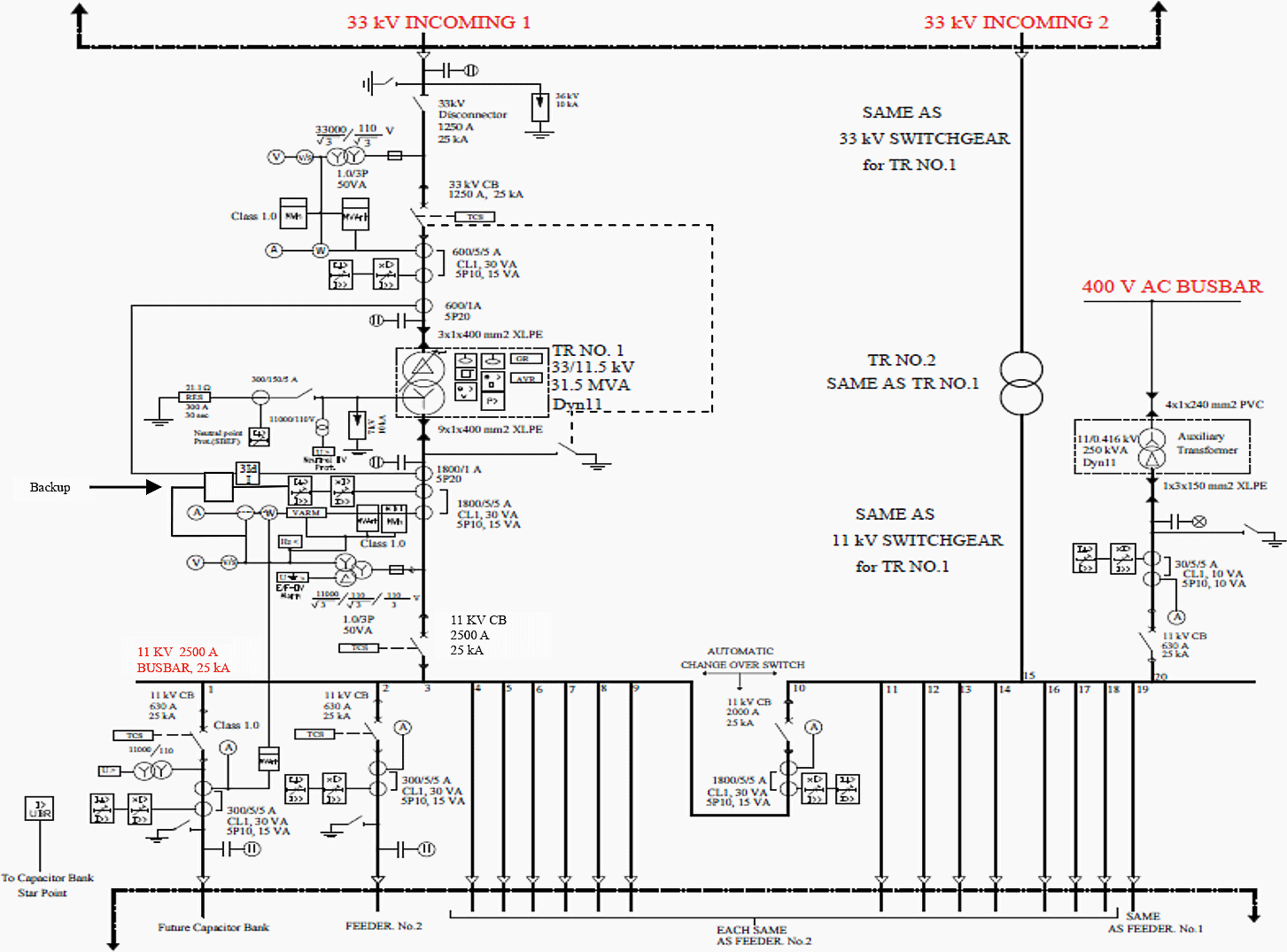
The 11 kV switchgear must be of the metal clad type suitable for indoor installation as per attached single line diagram. It consist of a single insulated busbar in air insulated busbar chamber metal clad, floor mounted unit, incorporating enclosures for the circuit breaker units, VTs, CTs and auxiliary wiring, relays, IEDs for SCS, port to SCADA of region DCC, potential transformers control switches, alarm lamps and indicating instruments and must be constructed in accordance with IEC 62271-1 and 62271-200.
The switchgear assembly consists of individually-grounded, compartmentalized steel structures. Each compartment has doors, barriers, and removable access panels to isolate the separate working functions.
The mimic diagrams showing the main components and their connections must be featured on the front panel of each switchgear compartment: 11kV – Red.
General Arrangement
The 11kV switchgear arrangement is made up of several interconnected functional units, as shown attached layout drawing of each substation. The 11 kV switchgear system must consist of the followings:
Twenty (20) switchgear panels such as:
- Two (2) incoming switchgear panel and
- One (1) bus section switchgear panel and
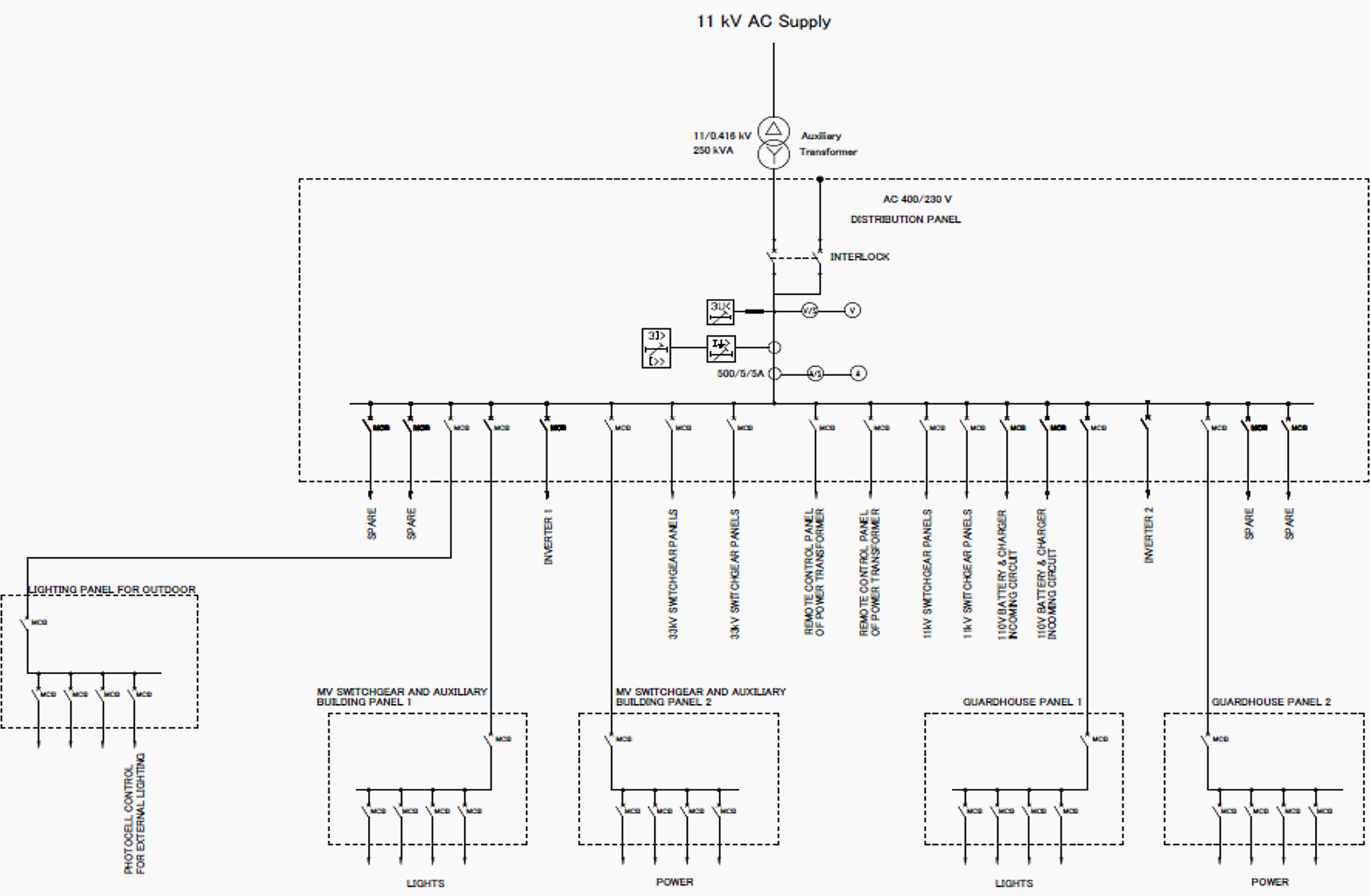
- One (1) auxiliary transformer switchgear panel,
- Two (2) future capacitor bank panel and
- Fourteen (14) outgoing switchgear panel.
Degree of protection
The degree of protection of persons against hazardous approach to live part must be IEC 60529.
- For enclosures: IP40
- For cable and breaker: IP41
- For instruments: IP50
- For busbar: IP51
Current Rating
Every current carrying part of the equipment including circuit breakers, current transformers, busbars, connection and joints must be capable of carrying its rated current continuously and in no part must the permissible temperature rise be exceeded, unless otherwise specified.
All current ratings specified are the minimum continuous values required under the service conditions specified in Service conditions section.
The circuit breaker ratings must be as follows:
- 2500A, 25 kA for transformer circuits
- 2500A, 25 kA for bus-section circuit
- 630A, 25kA for feeder circuits and auxiliary transformer circuit
Busbars and connection
The 11 kV switchgear must be of single copper busbar type, rated continuously 2500 Amps, the bus bars connections and branches must be suitably insulated by proper insulating material and must be of constant cross section area.
The busbar chamber is to be air insulated and must be of constant cross sectional area throughout their length with connection as short and straight as possible. Busbars must be contained in a separate compartment within the switchgear cubicle, but busbar barriers must be provided between switchgear equipment to prevent the spreading of ionized gases during faults.
Important! – Note for (GIS) substation:
- Fully insulated Busbar with all it’s branches and connection points with suitable insulation material.
- All the connections between the busbar and the C.B – SF6 chamber should be throuth fully insulated plug-in type connection.
Interesting reading related to MV switchgears:
Circuit breakers
The circuit breakers must comply with the requirements of IEC62271-100. The circuit breaker must be vacuum type, withdrawable type. The breaking capacity of the circuit breaker must be 25 kA.
Important! – Note for (GIS) substation:
- The life parts of vacuum circuit breaker and 3-position disconnector device (ON-OFF-Earth) should be insulated inside the SF6 chamber.
- All the connections to the busbar and to the line circuit should be done through plug-in bushings.
- All the switching operations can be done without opening the panel door.
- The circuit breaker should be vacuum type with life not less than 10,000 operations.
Interchange ability and isolation of circuit breaker
Circuit breakers of the same type and current rating must be interchangeable electrically and mechanically. The circuit breakers must incorporate horizontal isolation facilities and be mounted on horizontal draw-out trucks.
Each circuit breaker must be connected to the feeder circuit through plug and socket type isolating devices, the devices must be of the off load type but must be suitable for operation whilst the bars or feeder circuits are alive.
Interlocks
Disconnector connected in series with circuit breaker can close only when the circuit breaker opens and none of the adjacent earthing switches are closed. 36 kV earthing switch can close only when disconnector is opened.
All mechanical and electrical interlocks must be of the preventive type and must be arranged to prevent mal-operation. Interlocks must prevent any unsafe operation of the switchgear and must ensure that the operator follows safe and logical sequence of switching device operations.
Interlock arrangements must be as stated in 5.11 of IEC 62271-200.
| Title: | Technical specification for construction of 33/11 kV 2×31.5 MVA power substations – The Republic Of Iraq Ministry Of Electricity (MoE) Energy Distribution Office |
| Format: | |
| Size: | 5.4 MB |
| Pages: | 222 |
| Download: | Here 🔗 (Get Premium Membership) | Video Courses | Download Updates |
Suggested Study – Good operating practices for switchgear circuit breakers and contactors
Good operating practices for switchgear circuit breakers and contactors

Why in the high voltage side the CB has 1250 A while the current is about 600 A?
The same question for theow voltage side, why 2500 A for the CB while the current is about 1600 A.
I need to learn
What the main tests to be performed on the control panel and switch gear before it is commissioned ?
What I have seen is very impressive and a source of encouragement to Electrical Design Engineers especially at Medium and Low Voltage levels.
I am impressed!
I shall be visiting this site for reference in my Design assignments.
Why the last drawing in this file not appear well, Pls if there another copy clear than this send to me on
Alaazora93@gmail.com
It is better as I think to earth the neutral of the transformers through a reactance (single phase VT or single phase transformer) because the rating of the transformer is 31.5 MVA
Dear Ed
I have a doubt on mitigation of poor power quality. Is it recommended to keep UPS connected during a power fail and DG is running. Will it damage any components due to power quality
WE require 1600 kva 11/433 v oil type transformer schemaic line diagram