Good Cable Insulation
When voltage is impressed across any insulation system, some current leaks into, through, and around the insulation. When testing with DC high voltage, capacitive charging current, insulation absorption current, insulation leakage current, and by-pass current are all present to some degree.

For the purposes of this document on cable fault locating, only leakage current through the insulation will be considered. For shielded cable, insulation is used to limit current leakage between the phase conductor and ground or between two conductors of differing potential.
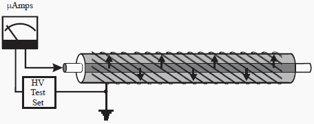
Cable insulation may be considered good when leakage current is negligible but since there is no perfect insulator even good insulation allows some small amount of leakage current measured in microamperes. See Figure 1.

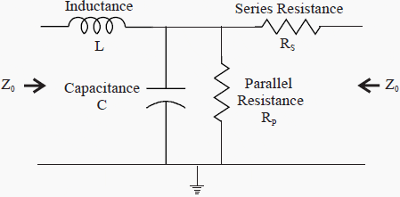
The electrical equivalent circuit of a good run of cable is shown in Figure 2. If the insulation were perfect, the parallel resistance RP would not exist and the insulation would appear as strictly capacitance.
Since no insulation is perfect, the parallel or insulation resistance exists. This is the resistance measured during a test using a Megger® Insulation Tester. Current flowing through this resistance is measured when performing a dc hipot test as shown in Figure 1.
The combined inductance (L), series resistance (RS), capacitance (C) and parallel resistance (RP) as shown in Figure 2 is defined as the characteristic impedance (Z0) of the cable.

When the magnitude of the leakage current exceeds the design limit, the cable will no longer deliver energy efficiently
| Title: | Fault Finding Solutions – MEGGER |
| Format: | |
| Size: | 2.4 Mb |
| Pages: | 44 |
| Download: | Right here | Video Courses | Membership | Download Updates |


This one of the greatest exposition site into the field of Electrical Engineering that has ever existed
i have a 16 m/m twin and earth cable laid in the ground over a distance of 500/meters load10/amps, it worked well for over a year and then all of sudden it tripped the c/b reset, then after 1/min it tripped again. No short, except when I tested with an amp/meter i noticed when i switch on the amps it started to climb rapidly, like a heating circuit , is it bad joints or installation break down, no idea please help ? Circuit controls a camera circuit, tested with megger shows dead short live neutral earth, no bang when engaging c/b stays engaged for short time?
Dear sir
THANKS FOR ALL INFORMATION YOU PROVIDE FOR US .
sir,
I am not been able to download article about powet transformer maintenance and condition monitoring
Good work
Very good article. As for the cable model, I must say that I’ve never seen this kind of cable equivalent circuit. Aren’t cables supposed to be symmetrical reciprocal systems? Input impedance should be the same from either end. Cable model is usually a Pi network consisting of half the values of both capacitance and parallel resistance on each end, plus a series resistance and inductance in the middle. The model shown here looks unsymmetrical. I think both series resistance and inductance should be added to both sides.
great work, very informative
Dear All,
This site is very usefull for all electrical engineer in true manner.
I complete my day at office after reading article send by your site.
I want to join in your site with articles and small Excel software developed by me.
I look forward to upgrade my knowledge.
Hello Sir,
I am new here in your site and I find it very informative and very helpful to me as a fresh electrical engineer. I just want to request for a topic about generators. The methods, principles, preventive maintenance and etc. will be very significant to me sir.
Many thanks,
Mark
Thanks for articles…
You’re welcome!