
Voltage potential tolerances
From early days to the development of modern power transmission system, lightning surges have been a source for troublesome operation of the grid. Faults, which affects the normal sinusoidal power system phases under operation and moreover faults that do permanent damage to equipment and facilities.
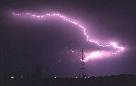
With short duration, a flash as shown in Figure 1, suddenly facilities are experiencing outages, with a varying consequence of a simple restart to days or even months of repairs. Even considering today’s understanding and protective measures in design, lightning still represents a source of damage and outages in the power transmission system.
More sensitive microprocessor-based equipment has been integrated into the power transmission system, requiring even more protective measures to ensure safe operation. On measure are to provide a proper design of grounding system to discharge an lightning surge efficiently.
The grounding systems are of fundamental importance in any electrical system. With a wide area of application, the grounding system is designed and optimized for the primary purpose and evaluation of severity.
When considering the high-voltage power transmission grid, a conventional method of power transfer consists of interconnected air insulated transmission lines, which often is terminated to a substation outdoor switchyard in both ends.
As function the substation may act as a hub, being the connection points for several transmission lines in a distribution center for factories and cities or serving a power plant as an infeed.
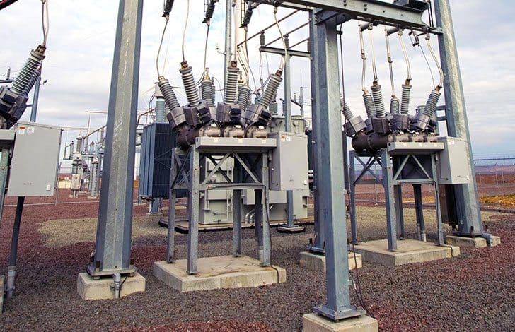
Being a central point in the power transmission and distribution chain involves handling high energy and strong electric fields. The main purpose of outdoor switchyard grounding system is to provide a low resistance path, at any point, to discharge high energy fault current at power frequency.
Also, the grounding grid is interconnected with the outside grounding system, lowering the total grounding resistance. With a buried grounding grid, the electrical discharge performance is dependent on soil parameters at the location in addition to grid configuration.
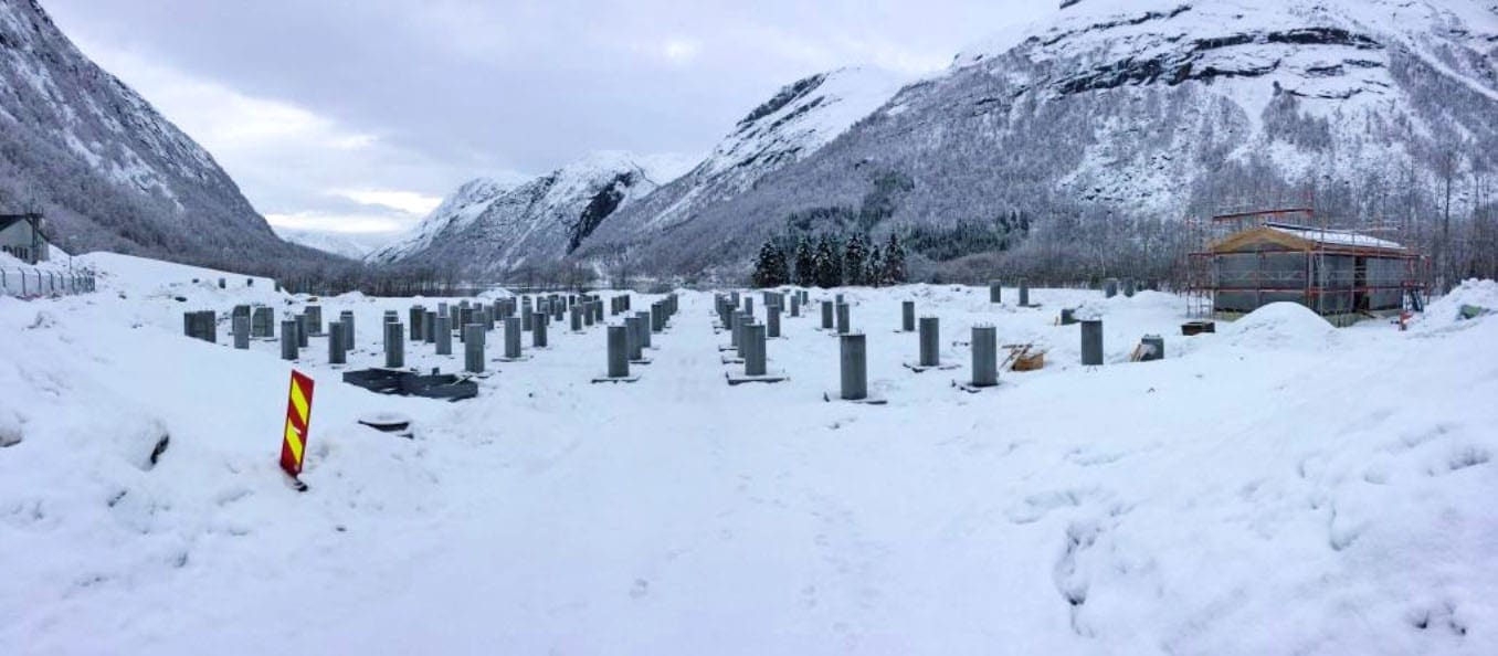
Chemical compound and type of soil will change slowly and anticipated to be a nearly fixed parameter, while the water content and temperature could change rapidly, affecting the grounding performance. To secure a level of stable and reliable soil resistivity for a switchyard, the construction method includes soil with high drainage factor, as an example consisting of a mix of rocks, clay and moraine gravel.
Figure 2 shows a 420 kV outdoor switchyard for a hydropower plant under construction which will use soil of this type. This gives high resistivity soil for the local region while securing the safety factors of the overall switchyard area.
A second important task for the grounding system is to discharge fast transients overvoltages, originating mainly from an external source of lightning strokes and internal as switching operations. Under fast transients current injections as lightning, the grounding system performs with a significantly different behavior than for current injections at power frequency.
While a power frequency current injection will utilize the entire grounding system, the steep front lightning transient will activate inductive effects which will limit the effective area of the grounding system during the steep rise time of the strike.
The lightning surge, with fast rise time, will propagate out in the ground grid; which will act as an antenna, inducing a large transient potential in the system. This short-term potential rise could lead to lower performance of protective equipment, and even malfunction or damage sensitive equipment. For this reason, the term grounding resistance is changed to impedance when describing the grounding system properties under transient conditions.
The ground resistance could be measured accurately by traditional methods to study power frequency performance; which is not the case under transient conditions.
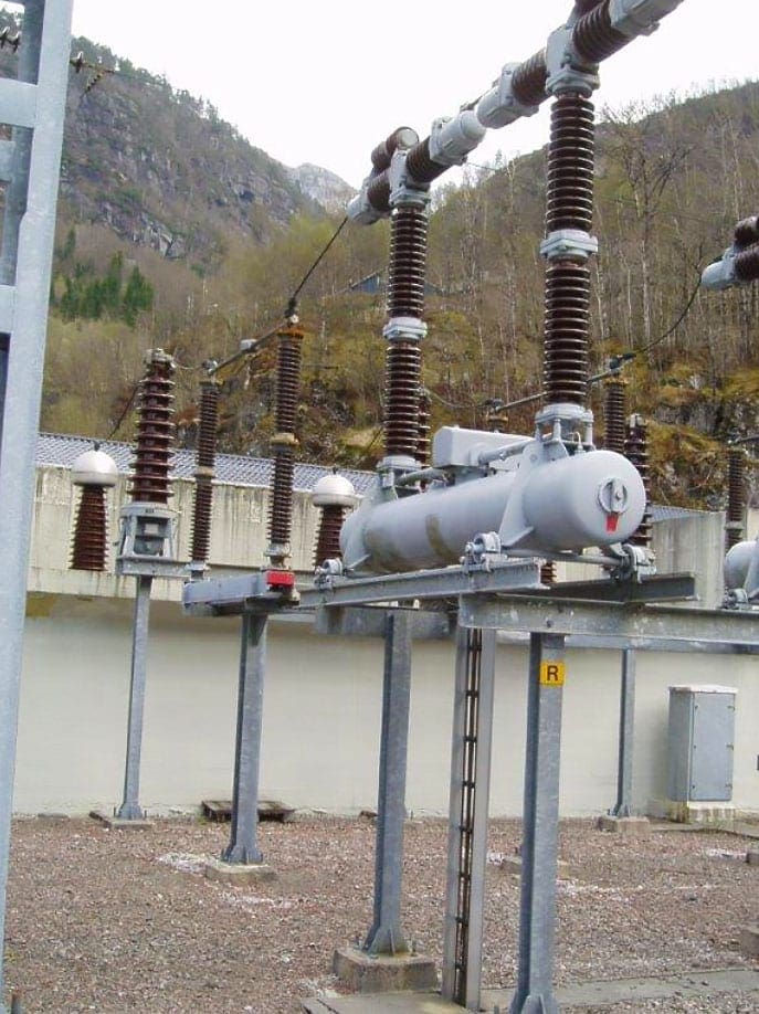
A facility case which deviates from design standards is typically found in larger domestic hydropower plants. A typical arrangement composes of one or more generators and transformers located in a rock cavity inside a valley mountain and connected to an outdoor switchyard. The main transformers are connected to a switchyard trough relatively long cables, typically several hundred meters long.
A typical infeed for a hydropower generator to an outdoor switchyard is shown in Figure 3.
The outdoor switchyard for hydropower facilities is most commonly also located in deep valleys which gives shielding for direct lightning strikes. However, located in remote locations the use of long overhead transmission lines is needed which makes the facility exposed to lightning surge entering from indirect strokes following the line.
Protective means for power transmission lines are a shielding design for direct lightning strikes. This is typically performed by having ground wires above the phases in the transmission line towers, to guide a direct strike to ground directly.
This is a design deviation where recommendation in standards is a placement of the surge arrester close to the transformer to avoid high voltage build-up caused by indirect lightning transient surge waves reflections.
The recommendation is described both in international standards as Institute of Electrical and Electronics Engineers (IEEE) “Application Guide for Surge Protection of Electric Generating Plants” and for domestic installation guidelines described by the Transmission System Operator (TSO) in “Statnett Earthing Guidelines”. The voltage build-up when selecting this design is well known and are considered in insulation coordination studies, where the overvoltages withstand level is determined.
Moreover, the grounding system will suffer a pulsating current injection from the surge arrester when selecting this design, mainly time-determined by the cable length. The situation of repetitive surge injections, with the fast front exciting the grounding system is not found documented.
If the present design is giving an additional factor, which may impact negatively on the switchyard equipment, is left to be discovered in this thesis.
| Title: | Transient behavior of substation grounding grids under lightning surges – Vegard Steinsland, Master Thesis in Energy, Electric Power Engineering at UNIVERSITY OF BERGEN |
| Format: | |
| Size: | 12.9 MB |
| Pages: | 168 |
| Download: | Here 🔗 (Get Premium Membership) | Video Courses | Download Updates |

Thank you for this nice presentation and distributing this work!
A summary of the method used in the thesis can also be found in the open journal paper
https://www.mdpi.com/1996-1073/12/16/3142
Very informative