
Maintenance Inspection Tasks
Despite there being many tests available to evaluate power transformer condition, experience shows that visual inspection is very effective, and sometimes the only way, to detect certain power transformer problems. Maintenance engineers know this. This best practice guide provides a list of the various inspections that may be applied to a power transformer, either in or out of service.

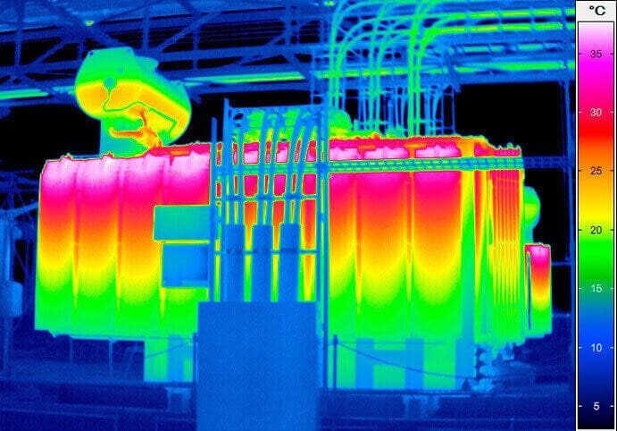
Infrared Thermography
Infrared thermography is a technique that provides an image of invisible infrared light emitted by objects due to their thermal condition without any direct contact with the scanned object. This technique can be used to detect a defective connection on transformer bushings, hot spots on surge arresters, blocked cooling systems, and circulating currents affecting localized overheating of the tank wall, or to confirm oil level.
For compartment type OLTCs, infrared thermography can sometimes detect abnormal heating of degraded contacts (coking, low pressure) or other malfunctions that cause temperature rise on the compartment.
Such problems are easily discerned on these OLTC designs because the OLTC compartment is normally cooler than the main tank, and any IR scan that shows to the contrary should trigger an investigation.
Main Tank and Conservator
The tank contains the transformer active element (core and coil assembly) and its insulating fluid. An on-load tap changer compartment can also be included in the assessment of tank condition. The integrity of the tank is dictated primarily by its mechanical characteristics. The tank must hold pressure and should not leak.
The integrity of the tank depends primarily on the condition of:
- the gasket containing surfaces,
- the hand hole, manhole, and tap changer door gaskets,
- and the integrity of tank welds.
The tank should also be inspected for indications of deformation. Tank deformation may result from extreme pressure or electrical arc experienced during a fault, improper foundation support, and for spare transformers, frequent installation and removal.
The integrity of a bladder may be checked in service by inserting a swab stick with a cotton cloth on the end through the bladder access port in the top of the conservator tank and gently swabbing the inside of the bladder. If the cotton swab becomes saturated with oil, this indicates that there is a leak in the bladder, and it must be replaced.
Transducers that can detect rupture include:
- A capacitive transducer that detects contact with oil
- A gas collection relay mounted in the head of the conservator to detect air
In the past, conservator tanks were not necessarily designed to withstand full vacuum. In these designs, whenever a vacuum is applied to the main tank, the valve between the main tank and the conservator tank must be closed. However, most modern conservator tanks are designed for full vacuum and the valve should be left open. In all cases, the transformer manual or manufacturer should be consulted.
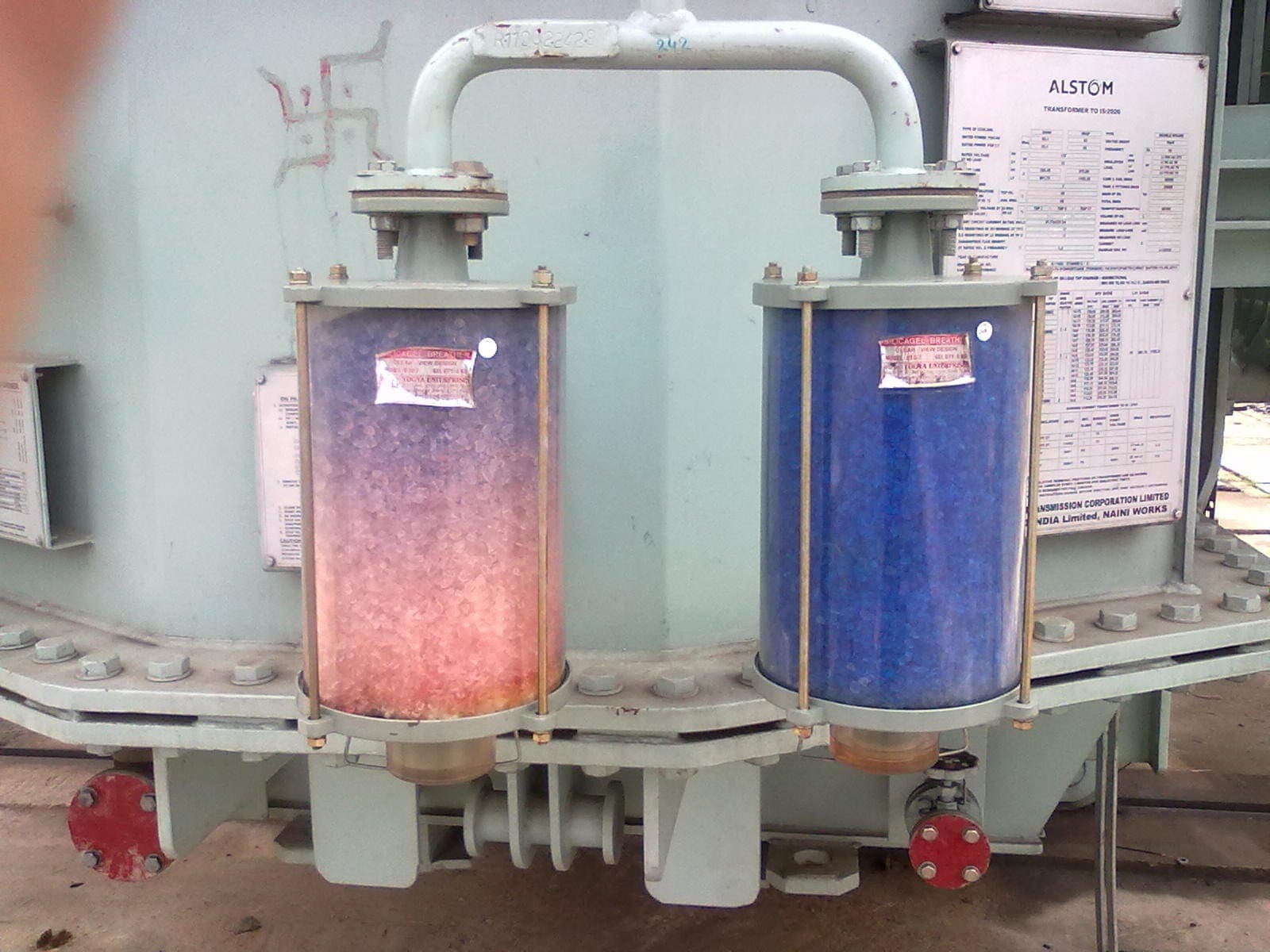
The desiccant for the bladder type conservator system should be checked regularly and replaced when it reaches the end of its moisture removal capability. Operating such a system with a non-functioning desiccant, (especially in a humid environment) can allow moisture to enter the tank, or cause the bladder to age prematurely.

The following actions can be performed on the main tank:
- Check for oil leaks, re-seal if necessary
- Check for paint damage and corrosion, repair if necessary
- Check oil levels in all compartments
- Check air drier and main conservator bladder – refill or replace if necessary
- Check air freezer – if installed
- Check grounding of the main tank and neutral terminals
- Check electrical insulation for tank base where fitted
- Check the status of all valves before putting back into service
Moreover, the color change should be observed to start from the fresh air input side only (where air first enters the breather on its pathway toward the conservator). If the silica gel changes color on the conservator side of the breather, or if the color of the silica gel remains unchanged after several months, then this indicates there is air leakage in the connection piping allowing air to bypass the breather.
Cooling System
Oil Pumps
Visual inspection of the transformer oil cooling circuit components should be performed regularly and usually not exceeding every 12 months. Oil Pumps should be manually energized to ensure proper operation. Any significant noises (grinding, rubbing, scraping, oil flow cavitation) should be noted, investigated further, and corrected. Flow gauges should indicate full flow without fluctuation. All areas including piping, valves and the surrounding ground area must not show evidence of oil leakage.
Pumps equipped with a bearing condition monitor should have readings taken annually to ensure bearing integrity. Pumps with ball bearings are particularly vulnerable to in-service failure. Therefore, their replacement by pumps with sleeve bearings should be considered.

Radiators and Fans
Fans should be manually energized to ensure proper operation. Similarly to the oil pumps, significant fan motor noise or fan imbalance shudder should be noted, investigated further, and corrected. Fan blade guards must be maintained for the safety of personnel. Obvious obstructions to the through airflow caused by debris should be noted and cleaned.
Periodic infrared imaging of the radiators should be made to ensure proper oil flow and heat transfer. All areas including piping, valves, and the surrounding ground area must not show evidence of oil leakage.
Typical oil leakage points include pipe work flange joints, valve stems, oil pump electrical connections, radiator headers, and air bleed plugs.
Forced Oil-Air Coolers
Forced Oil-Air Coolers are used on many generator step-up transformers and mobile transformers, and some substation transformers. These coolers depend upon both the full airflow from their fans and full oil flow from their associated pumps, in order to provide the amount of cooling required to dissipate the transformer losses.
Without both the fans and pumps operating, these coolers are essentially non-functional. Depending on the environmental conditions where the transformer is in service, after several years the coolers may deteriorate to the extent that they approach their end of life. One or more of the following conditions may cause the premature end of life for these coolers.
Transformer Cabinets
As most accessories are connected through the Transformer Cabinet, this component requires special attention. The following inspection tasks are suggested:
- Check power supply, back-up feed, and its signaling
- Check functionality of anti-condensation heaters
- Tighten screws and clean contacts on all current-carrying parts
- Check service hour counter, if installed

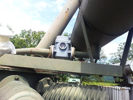
Buchholz Relay Operation and Recommended Actions when It Operates
This section provides guidance on the possible causes of Buchholz relay operation and recommends actions following the receipt of a Buchholz surge trip or gas collection alarm. It covers both operational situations and situations that arise during the commissioning of new transformers.
Buchholz relays installed on the transformer main tank have two elements described in more detail below:
Gas Collection Element
This element collects any gas escaping from the transformer and closes a contact when the gas volume reaches a certain limit. If gas continues to be produced after this limit is reached, it will escape out of the relay into the conservator and no further operation will take place. The transformer should have been carefully designed to avoid any internal pockets where gas can collect so that any gas bubbles will rise through the pipework to be collected in the relay.
The gas collection element operates when a certain volume of gas is collected. Therefore it gives no direct indication of the rate of gas production.

Oil Surge Element
Primarily, this element is pre-set to operate and close contact at a certain oil velocity through the relay. This will correspond to the oil flow expected during an arcing fault where oil surges from the main tank towards the conservator.
However, this element will not operate on gas collection because the relay is designed to accumulate only a set volume of gas before allowing all excess gas to pass on to the conservator. This releases the excess gas before it can reach the level of the surge element float, allowing an oil surge event to be discriminated from a gas collection event.
Secondly, if for any reason the oil level in the relay should drop (for example if the oil is escaping from the transformer and the oil level drops below the level of the relay), then this element will also operate.
| Title: | Best practice guide for power transformer maintenance – Working Group A2.34 (C. Rajotte ( CA) – (Convener), TF Leaders: M. Foata (CA), P. Jarman (UK), F. Larese (FR), P. Lorin (CH), B. Pahlavanpour (UK), J.P. Patelli (FR), J. Velek (CZ), R. Willoughby (AU), R. Barrento (PT), P. Boman (US), I. Diaconu (RO), A. Drobyshevski (RU), Y. Ebisawa (JP), T. Fagarasan (RO), N. Fantana (DE), H. Gago (ES), J. Gebauer (DE), P. Gervais (CA), M. Krüger (AT), G. Lawler (IR), R. Maina (IT), C. Moldoveanu (RO), P. Mueller (CH), D. Olan (CA), L Paulhiac (FR), M. Pena (BR), E. Perez-Moreno (ES), S. Quintin (ES),V. Samoilis (GR), F. Simon (FR), A. Shkolnik (IS), B. Sparling (CA), P. Warczynski (PL)) |
| Format: | |
| Size: | 2.12 MB |
| Pages: | 123 |
| Download: | Here 🔗 (Get Premium Membership) | Video Courses | Download Updates |


I know about your company for the long time and I really admire it. I believe I can make a positive impact here. The company value are line which my own as electrical engineer. I love what I heard or read about the company services and culture.
Very useful guide .
hi
can you explain precaution of live transformer maintenance and earth resistance measurements