
Partial Discharge Measurements
Purpose of measurement
A partial discharge measurement (PD‐measurement) is a nondestructive tool used to establish the condition of a transformer insulation system. The goal of partial discharge measurement is to certify that no harmful partial discharge sources exist.
A PD‐measurement makes it possible to detect and localize areas within the transformer which are exposed to elevated dielectric stresses, i.e. stresses which in the long run can be harmful to safe transformer operation.
Partial discharge measurements are explicitly specified in standards or in customer specifications. They are to be carried out in conjunction with dielectric tests in high voltage laboratories using AC‐voltage in the power frequency range. For HVDC transformers PD measurements are also carried out on dielectric tests with DC‐voltages.
For on‐site PD measurements (for example on repaired transformers) other types of PD‐free excitation may also be carried out.
NOTE! Partial discharge measurement should generally be the last dielectric test conducted on the transformer.
General
Partial discharge is a partial voltage breakdown within a series of insulating elements between two electrodes of different potential, (capacitances C2’ and C3’, see Figure 1). During a typical PD measurement, the magnitude of the detectable value of partial discharge activity is recorded as a function of the applied voltage.
For very fast changes, or during the first instant after charge movement, the individual insulation links in a series of connected links between two line terminals can be regarded as a number of series connected capacitors.
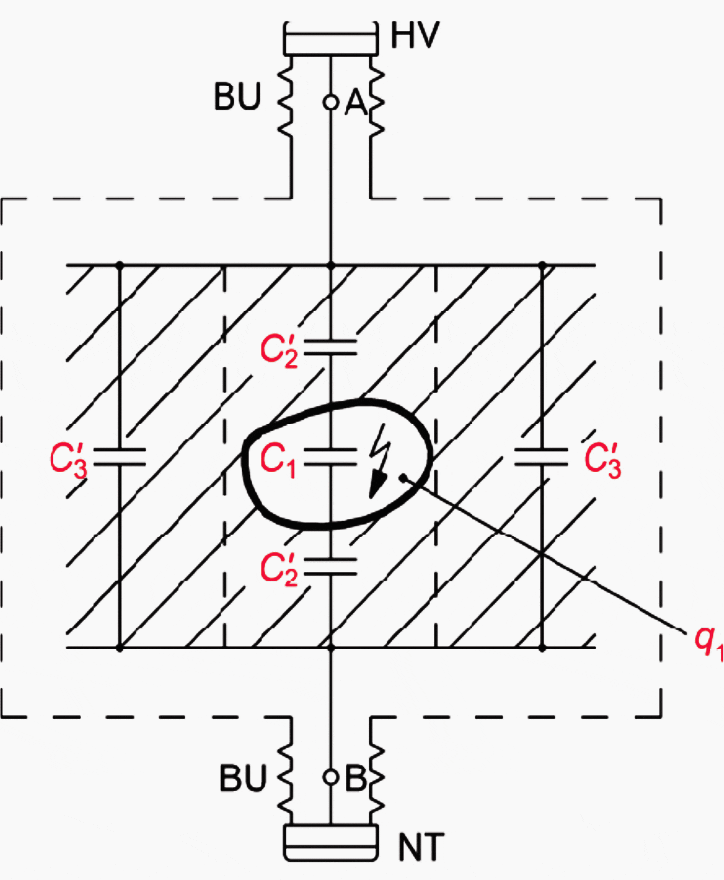
Where:
- BU = bushing
- HV = high voltage
- NT = neutral terminal
- C1, 2, 3 = active part of transformer (including oil)
- C1 = weak region
- Ct = test object capacitance (C’2 and C’3)
If the two line terminals are connected together via an external capacitor Ck, see Figure 2, the charge movements within the series‐connected insulation links (capacitances C’2 and C’3, see Figure 1) will also be reflected in the charge of external capacitor Ck.
The charge movements can be detected as circulating current impulses i(t) in the parallel‐connected capacitors Ck and Ct, see Figure 2.
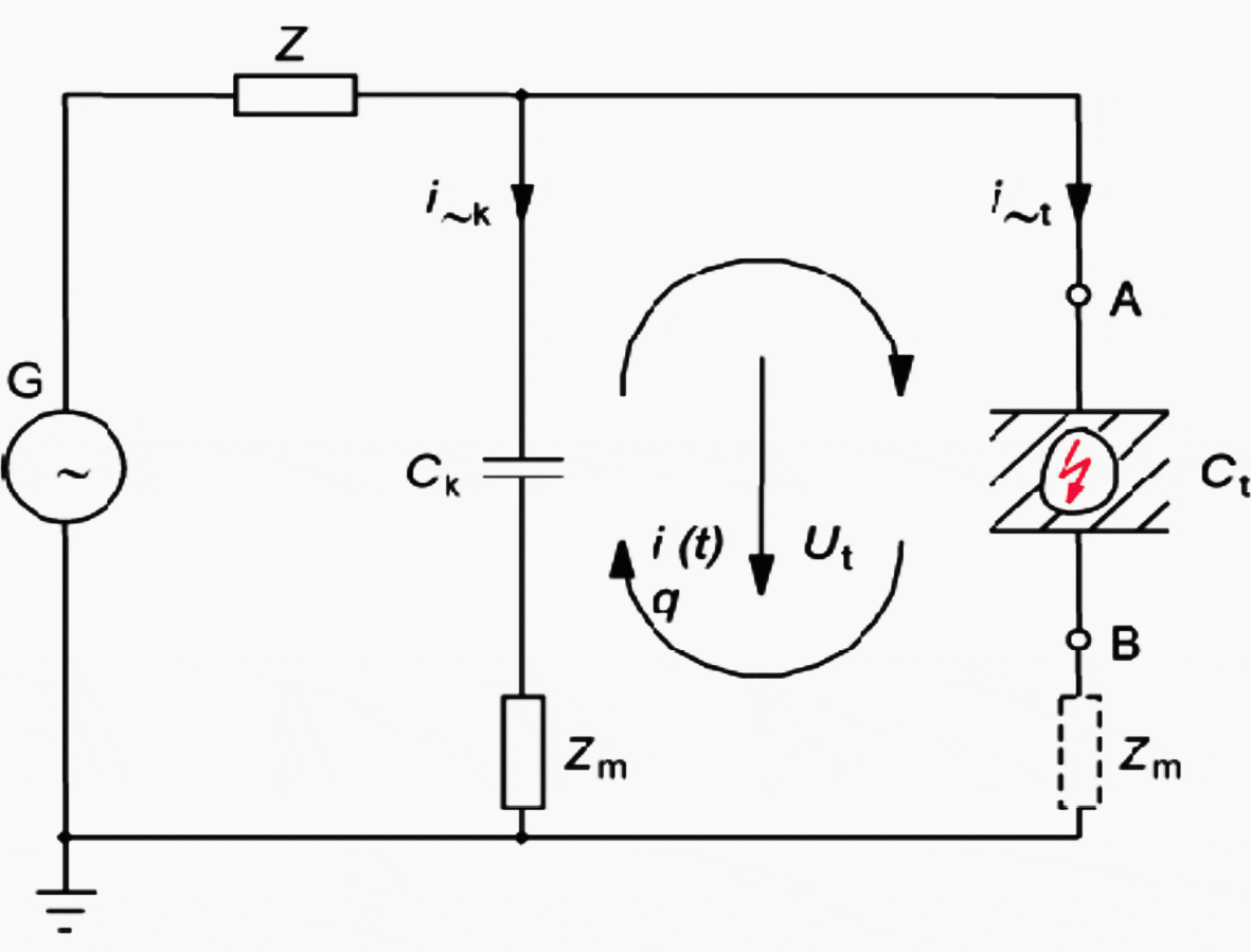
Where:
- Ct = test object capacitance
- Ck = coupling capacitor
- G = voltage source
- i(t) = PD current pulses
- i~k,~t = displacement currents
- Z = voltage source connectors
- Q = transferred charge
- Ut = voltage at parallel‐connected capacitors
- Zm = measuring impedance
Two requirements must be fulfilled to initiate a partial discharge (i.e. electric breakdown) within the weak region of an extended insulating system:
- Local electric field stress E in the weak region must be greater than the inception electric field of the PD Source.
- Free electrons must be available to initiate the electric breakdown.
Excessive stress in the weak region can result from design flaws, contamination or deviation from permissible tolerances in the manufacturing process, insulating material flaws, etc.
All PD measuring methods are based on the detection of PD current impulses i(t) circulating in the parallel‐connected capacitors Ck (coupling capacitor) and Ct (test object capacitance) via measuring impedance Zm. The basic equivalent circuit for PD measurements is presented in Figure 2.
The measuring impedance Zm can either be connected in series with coupling capacitor Ck or with the test object capacitance Ct.
As discussed, PD current impulses are generated by charge transfers between parallel‐connected capacitor Ck (coupling capacitor) and Ct (test object capacitance).
| Title: | Power transformer testing procedures and schemes – MTEKPRO Technologies Pvt. Ltd |
| Format: | |
| Size: | 7.2 MB |
| Pages: | 96 |
| Download: | Right here | Video Courses | Membership | Download Updates |


highly helpful
Partial Discharge the is Terminology is not simple to understand but by practical way conducting the various experiments and measurements, gaining some experience knowledge through that.
I hope that you fo the same but in frensh too.
Good