The Requirements of BFP Schemes
Since the BFP operation will trip a number of adjacent CBs, the consequence of its mis-operation is usually severe. In some cases, the BFP mis-operation was the starting point of cascading outage in the area.

On the other hand, if the BFP does not operate to isolate the fault, the system is at risk too and some equipment such as generator and transformer could be damaged. Therefore, a good BFP design should be able to prevent mis-operation due to single component failure or single human error.
It is desirable to achieve both security and dependability at the same time.
The Line BFP may need to bias towards security while the Bank BFP need to bias towards sensitivity and dependability.
Breaker failure protection practices in utilities
This section reviews the BFP designs in three Utilities from the implementation point of views such as the BFP initiation, fault detector settings, the BFP timer settings, tripping circuits, system restoration design, direct transfer trip (DTT), etc.
A. BFP design in Utility-1
1. BFP Implementation
In Utility-1, most CBs at transmission level have dedicated BFP scheme that is based upon a stand-alone digital relay for each CB. The relay also includes other control and monitoring functions such as Auto Reclosing, CB control, CB alarms, trip circuit monitoring etc.
In the past several years, this Utility has extended the installation of dedicated BFP to subtransmission level at 69kV.
2. BFP Initiation
All protection devices/relays that trip the CB also initiate BFP except trips from another BFP Lockout relay operation. The BFP initiation signals from protective relays are hardwired to the inputs of the dedicated CB Control and Failure relay.

3. BFP Logic
Residing in the dedicated CB control relay, the BFP logic includes the following three components:
- Current Detector (50P or 50G),
- CB Failure Initiation (BFI) and
- CB Failure Timer (tBF).
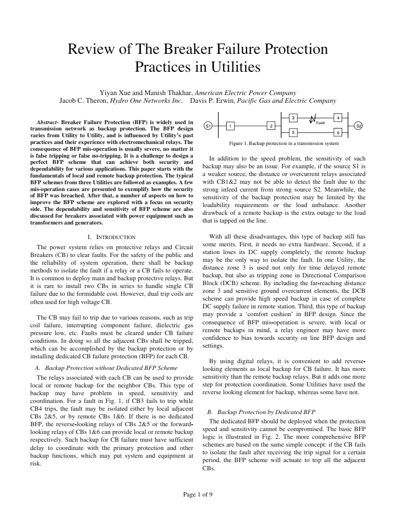
This simple BFP logic is inherited from EM relay design. As shown in Fig. 1, the BFP scheme is armed if the current detector (50P or 50G) is actuated and the breaker failure initiation (BFI) signal is presented.
If these conditions persist after BFP timer expires, the BFP will pick up the lockout relay (LOR) to trip all the adjacent CBs.
This Utility has DTT facilities installed for lines over 200kV, or for some generator interconnections. For lines below 200kV, the local relays are set to back up the remote CB.
For example, a far-reaching distance zone 3 and sensitive ground overcurrent used in a DCB scheme can backup the failed CB in remote station if the blocking signal is absent.
| Title: | Review of The Breaker Failure Protection Practices in Utilities – Yiyan Xue and Manish Thakhar (American Electric Power Company), Jacob C. Theron (Hydro One Networks Inc.) and Davis P. Erwin (Pacific Gas and Electric Company) |
| Format: | |
| Size: | 225.2 KB |
| Pages: | 9 |
| Download: | Right here | Video Courses | Membership | Download Updates |


This is really advantage information
It is a very good presentation.