
Overcurrent relays
The basic element in overcurrent protection is an overcurrent relay. The ANSI device number is 50 for an instantaneous overcurrent (IOC) or a Definite Time overcurrent (DTOC) and 51 for the Inverse Definite Minimum Time.
There are three types of operating characteristics of overcurrent relays:
- Definite (Instantaneous)-Current Protection,
- Definite-Time Protection and
- Inverse-Time Protection.
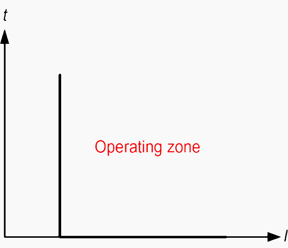
1. Definite (instantaneous)-current protection
This relay is referred as definite (instantaneous) overcurrent relay. The relay operates as soon as the current gets higher than a preset value. There is no intentional time delay set. There is always an inherent time delay of the order of a few milliseconds.
The relay setting is adjusted based on its location in the network. The relay located furthest from the source, operates for a low current value.
In the feeder with small impedance, distinguishing between the fault currents at both ends is difficult and leads to poor discrimination and little selectivity at high levels of short-circuit currents.
While, when the impedance of feeder is high, the instantaneous protection has advantages of reducing the relay’s operating time for severe faults and avoiding the loss of selectivity.
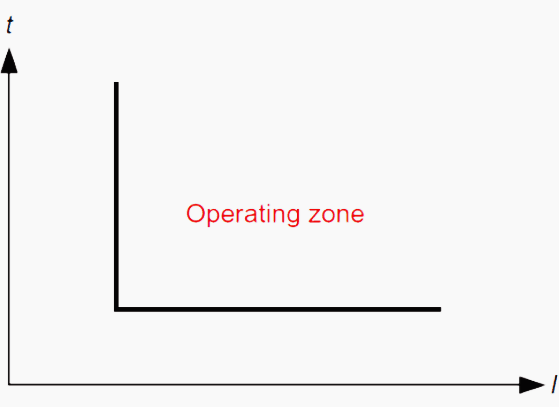
2. Definite-time protection
In this type, two conditions must be satisfied for operation (tripping), current must exceed the setting value and the fault must be continuous for at least a time equal to the time setting of the relay.
Thus, is has a time setting and pick up adjustment. Modern relays may contain more than one stage of protection each stage includes each own current and time setting.
The settings of this kind of relay at different locations in the network can be adjusted in such a way that the breaker closest to the fault is tripped in the shortest time and then the other breakers in the direction toward the upstream network are tripped successively with longer time delay.
The disadvantage of this type of protection is that it’s difficult to coordinate and requires changes with the addition of load and that the short-circuit fault close to the source may be cleared in a relatively long time in spite of its highest current value.
Definite time overcurrent relay is used as a backup protection of distance relay of transmission line with time delay, backup protection to differential relay of power transformer with time delay and main protection to outgoing feeders and bus couplers with adjustable time delay setting
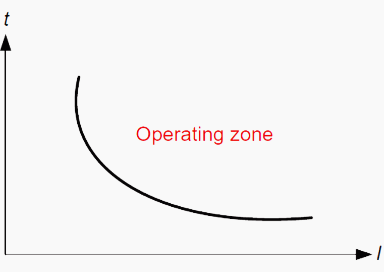
3. Inverse-Time Protection
In this type of relays, operating time is inversely changed with the current. So, high current will operate overcurrent relay faster than lower ones.
They are available with standard inverse, very inverse and extremely inverse characteristics.
The operating time of both overcurrent definite-time relays and overcurrent inverse-time relays must be adjusted in such a way that the relay closer to the fault trips before any other protection. This is known as time grading.
The difference in operating time of these two relays for the same fault is defined as discrimination margin. The adjustment of definite-time and inverse-time relays can be carried out by determining two settings: time dial setting and pickup setting.
The time dial setting adjusts the time delay before the relay operates whenever the fault current reaches a value equal to, or greater than, the relay current setting.
| Title: | The Basics Of Overcurrent Protection – Seminar Paper – Genc Baruti |
| Format: | |
| Size: | 1.20 MB |
| Pages: | 20 |
| Download: | Right here | Video Courses | Membership | Download Updates |


I would like to receive the protection material such as this.
Dear Sir/Madam,
I’d like to make connection with your company.
Regards,
Tesfaye H. (Electrical Engineer).