
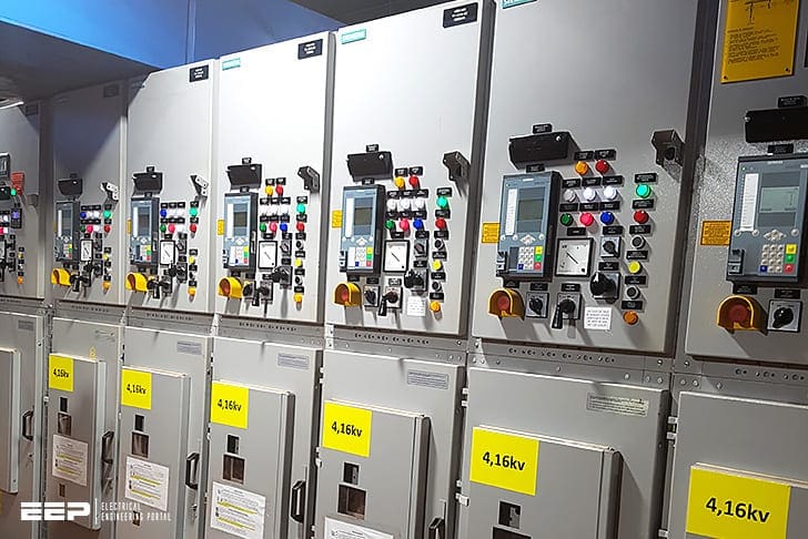
MV switchgear busbars
If the switching principle has not yet been defined during network planning or in accordance with operator specifications, some general aspects should be taken into account to help reach a decision of a right medium voltage switchgear.
And these are:
Selection variable: single / double busbars, bus section panel, bus section panel / transfer panel with switch or circuit-breaker or bus coupler unit (with double busbar).
Key influencing factors for the right decision of a MV switchgear are: line structure, line protection, tripping times and selectivity, reserves / availability, switchover time, operating procedures, in-plant generation, emergency supply or power quality (unstable loads).
MV switchgear with single busbars
A single busbar is suitable for most supply duties. In systems with a higher number of feeder circuits, the busbars can be sub-divided into sections each with their own infeed. In this way, each section can potentially draw a reserve supply from an adjacent section.
- it is completely transparent in all switching states;
- as a result, it is easy to use if network failures need to be rectified urgently, which greatly reduces the risk of switching faults;
- if switchovers caused by faults need to be carried out, only the circuit-breakers need to be operated.
If the wrong circuit-breaker is operated inadvertently, this will not affect safety of the switchgear because circuit-breakers can make or break all load and short-circuit currents, even during earth fault and under any other fault conditions.
MV switchgear with double busbars
For technical or contractual reasons, some requirements can only be properly fulfilled by means of double busbars, for example if:
Example #1 – If two (or more) infeeds must always be operated separately (e.g. infeeds from different public utility companies or the strict separation of in-plant generation and the public network);
Example #2 – If loads can interfere with the power quality when causing voltage fluctuations or flickers, and other equipment is sensitive to those interferences.
Example #3 – If loads of different importance need to be distributed across “safe” and “less safe” busbars (i.e. busbars with different requirments on the availability);
Example #4 – If a network must be divided into two sub-networks due to the limited short-circuit strength of the installed equipment. Switchovers permit to balance fluctuating load current consumption.
Design of double busbars
The lifetime of a disconnector plays an important role for double busbar switchgear. If frequent switchovers are required, disconnectors should not be integrated in the switchover process due to their relatively short operating cycle lifetime.
The average mechanical endurance of a disconnector (drawout unit or truck) is 1000 or 2000 operating cycles, corresponding with classes M0 and M1 (IEC 62271-102).
Only the designs B1 and B2 suit the requirements for frequent busbar switchover. Only the circuit-breakers are operationally switched, the disconnectors are opened only for maintenance or work purposes.
In contrast to this, the classic double busbar design (A) is less suitable since every busbar switchover implies to operate the disconnectors.
| Title: | Medium voltage switchgear application guide (selection, switching duties, configurations) – Dipl. Ing. Ansgar Müller at Siemens |
| Format: | |
| Size: | 1.50 KB |
| Pages: | 135 |
| Download: | Right here | Video Courses | Membership | Download Updates |

Thank You Sir, Thank You So Much.
Thank you for all information available for electrical engineers, valuable information to teach all the users of the EEP Electrical Engineering Portal.
Best Regards
Jorge Torrico
You’re welcome Jorge!