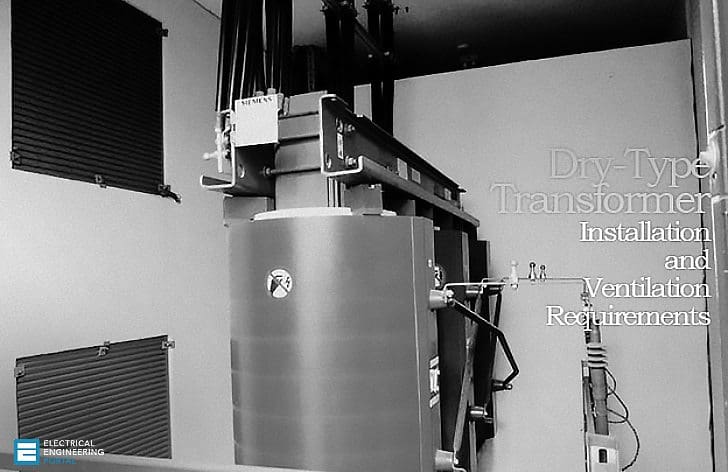
Installation
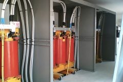
Dry-type transformers should be installed over foundations that are properly leveled and capable to withstand their weight.
When a transformer is fitted with wheels, make sure the equipment will be equally supported on its base points in order to assure its stability and to prevent any deformation.
When installing the transformer, the following factors should be carefully taken in account:
1. There should be a minimum spacing of 0,5 m between one transformer and another, and between the transformer and any adjacent wall in order to facilitate the access for inspection and ventilation, depending, however, on the project dimensions and the voltages;
2. The room where the transformer will be installed should be well ventilated as to assure proper natural ventilation, since this is an essential parameter for a proper performance of a dry transformer.
In this regard, it is important that the air inlets are located at the front part of the transformer near the bottom and the air outlets are located at the back part of the transformer, with near the top openings large enough to allow for a circulation of approx. 2,5 cubic meters of air per minute/kW of loss. (See the example calculation below).
Proper ventilation in the transformer room will grant the expected useful life and stable operation either on continuous regime or under momentary overloads.
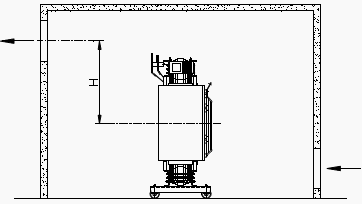
As normally the natural ventilation is not sufficient, fans can be installed to increase the air flow i n the room according to Figure 2 or, preferably, adopt the refrigeration o f the room where the transformer will operate .

To calculate the approximate size of the openings or the airflow necessary in the room the following expressions cab be used, considering a difference of 15ºC between the inlet air and the outlet air.
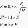
where:
Pt = total transformer losses sinked at 115°C [kW]
S = lower opening surface [m2]
S’ = upper opening surface [m2]
H = distance measured between the middle of the height of the transformer and the middle of the upper opening for air outlet [m]
V = cooling air volume[m3/min]
Example: Installation of two 2.000 kVA dry-type transformers
- Typical total losses PT for 2 MVA dry-type transformer at 115ºC = 27kW
- Distance H between the middle of the transformer height and the middle of the air upper outlet opening: 1,5m

From the calculated area we know that the installation of forced ventilation in the room will be necessary.
The minimum flow of the fans will be:
![]()
This example does not consider the presence of a protection cabinet, wich would be put in questi on in the case of a proper room for the transformer installation.
Reference: Instruction Manual For Dry-type Transformers – WEG









Hi Guys
The formulars for determining the inlet and outlet opening surfaces are they only applicable on natural airflow, can I use them still for forced airflows
Send me notificatios of new technical articles and guides
In the example, S is calculated as S=0.3*27*2/sqrt(1.5); why the factor 2 and not just S = 0.3*27/sqrt(1.5) as in the formula.
Because there are 2 transformers not just one .
> Can share the calculation for the enclosure IP23 Class
Is there any standard or compliance for height of foundation for dry type transformer to be kept in a room?
Well, you said that airflow could be “2,5 cubic meters of air per minute/kW of loss.” But fundamental question is why 2,5? Why not 2 or 3? Or 2,75? Is there some technical requirement? I am asking because I do not know about any. In IEC 61936-1:2010/Cor.1:2011 there is nothing about.
You are right. Actually you will have to calculate amount of air required to drain off the heat. You will have to assume outlet temperature of air. Then velocity will depend on this volume. Each fan can impart fixed velocity to the air or it can drain fixed amount of air. Hence velocity will depend on the type of the.fan
Good Article!
Great Article, thanks for sharing. In your example the calculation for the fresh air volume it should be 2.5 x 27 x 2 according to the text in the installation section.