
Provision of earth fault protection
One of the most common faults to occur on a motor is a stator winding fault. Whatever the initial form of the fault (phase phase, etc.) or the cause (cyclic overheating, etc.), the presence of the surrounding metallic frame and casing will ensure that it rapidly develops into a fault involving earth.
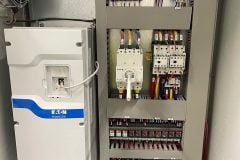
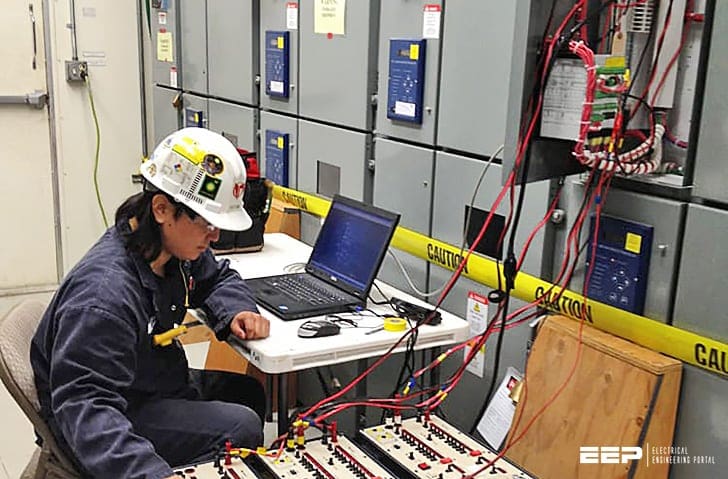 Earth fault protection of an AC motor in 4 different earthing systems (ob photo: Engineer testing the SEL-710 motor protection relay in a 2.4kV motor control center)
Therefore, provision of earth fault protection is very important. The type and sensitivity of protection provided depends largely on the system earthing, so the various types will be dealt with in turn.
It is common, however, to provide both instantaneous and time-delayed relay elements to cater for major and slowly developing faults.
Contents:
- Solidly-earthed system
- Resistance-earthed systems
- Insulated earth system
- Petersen coil earthed system
- HV motor earth-fault protection example
1. Solidly-Earthed System
Most LV systems fall into this category, for reasons of personnel safety. Two types of earth fault protection are commonly found – depending on the sensitivity required.
A lower limit is imposed on the setting by possible load unbalance and/or (for HV systems) system capacitive currents.
Care must be taken to ensure that the relay does not operate from the spill current resulting from unequal CT saturation during motor starting, where the high currents involved will almost certainly saturate the motor CT’s.
It is common to use a stabilising resistor in series with the relay, with the value being calculated using the formula:
where:
- Ist = starting current referred to CT secondary
- I0 = relay earth fault setting (A)
- Rstab =stabilising resistor value (ohms)
- Rct = dc resistance of CT secondary (ohms)
- Rl =CT single lead resistance (ohms)
- Rr = relay resistance (ohms)
- k = CT connection factor (1 for star point at CT, 2 for star point at relay).
The effect of the stabilising resistor is to increase the effective setting of the relay under these conditions, and hence delay tripping.
An alternative technique, avoiding the use of a stabilising resistor is to use a definite time delay characteristic. The time delay used will normally have to be found by trial and error, as it must be long enough to prevent maloperation during a motor start, but short enough to provide effective protection in case of a fault.
Co-ordination with other devices must also be considered.
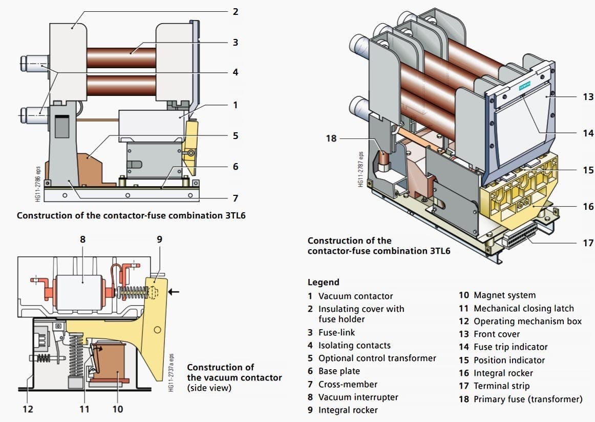
A common means of supplying a motor is via a fused contactor (Figure 2). The contactor itself is not capable of breaking fault current beyond a certain value, which will normally be below the maximum system fault current – reliance is placed on the fuse in these circumstances.
As a trip command from the relay instructs the contactor to open, care must be taken to ensure that this does not occur until the fuse has had time to operate.
Figure 3(a) illustrates incorrect grading of the relay with the fuse, the relay operating first for a range of fault currents in excess of the contactor breaking capacity. Figure 3(b) illustrates correct grading. To achieve this, it may require the use of an intentional definite time delay in the relay.
If a more sensitive relay setting is required, it is necessary to use a core-balance CT (CBCT). This is a ring type CT, through which all phases of the supply to the motor are passed, plus the neutral on a four-wire system. The turns ratio of the CT is no longer related to the normal line current expected to flow, so can be chosen to optimize the pick-up current required.
Magnetising current requirements are also reduced, with only a single CT core to be magnetised instead of three, thus enabling low settings to be used.
Figure 4 illustrates the application of a core-balance CT, including the routing of the cable sheath to ensure correct operation in case of core-sheath cable faults.
2. Resistance-Earthed Systems
These are commonly found on HV systems, where the intention is to limit damage caused by earth faults through limiting the earth-fault current that can flow.
Two methods of resistance earthing are commonly used: low resistance and high resistance earthing. Let’s explain one by one.
2.1 Low resistance earthing
In this method, the value of resistance is chosen to limit the fault current to a few hundred amps – values of 200A-400A being typical.
With a residual connection of line CT’s, the minimum sensitivity possible is about 10% of CT rated primary current, due to the possibility of CT saturation during starting.
The setting should not be greater than about 30% of the minimum earth fault current expected. Other than this, the considerations in respect of settings and time delays are as for solidly earthed systems.
2.2 High resistance earthing
In some HV systems, high resistance earthing is used to limit the earth fault current to a few amps. In this case, the system capacitive charging current will normally prevent conventional sensitive earth fault protection being applied, as the magnitude of the charging current will be comparable with the earth fault current in the event of a fault.
The solution is to use a sensitive directional earth fault relay.
A core balance CT is used in conjunction with a VT measuring the residual voltage of the system, with a relay characteristic angle setting of +45ºC. The VT must be suitable for the relay and therefore the relay manufacturer should be consulted over suitable types – some relays require that the VT must be able to carry residual flux and this rules out use of a 3-limb, 3-phase VT.
A setting of 125% of the single phase capacitive charging current for the whole system is possible using this method. The time delay used is not critical but must be fast enough to disconnect equipment rapidly in the event of a second earth fault occurring immediately after the first.
An alternative technique using residual voltage detection is also possible, and is described in the next section (below).
3. Insulated Earth System
Earth fault detection presents problems on these systems since no earth fault current flows for a single earth fault. However, detection is still essential as overvoltages occur on sound phases and it is necessary to locate and clear the fault before a second occurs.
Two methods are possible:
- Detection of the resulting unbalance in system charging currents
- Residual overvoltage.
3.1 System charging current unbalance
Sensitive earth fault protection using a core-balance CT is required for this scheme. The principle is the same as already detailed, except that the voltage is phase shifted by +90ºC instead of -90ºC.
To illustrate this, Figure 5 below shows the current distribution in an Insulated system subjected to a C-phase to earth fault and Figure 6 the relay vector diagram for this condition.
The residual current detected by the relay is the sum of the charging currents flowing in the healthy part of the system plus the healthy phase charging currents on the faulted feeder – i.e. three times the per phase charging current of the healthy part of the system.
As there is no earth fault current, it is also possible to set the relay at site after deliberately applying earth faults at various parts of the system and measuring the resulting residual currents.
If it is possible to set the relay to a value between the charging current on the feeder being protected and the charging current for the rest of the system, the directional facility is not required and the VT can be dispensed with.
3.2 Residual voltage method
A single earth fault results in a rise in the voltage between system neutral and earth, which may be detected by a relay measuring the residual voltage of the system (normally zero for a perfectly balanced, healthy system). Thus, no CTs are required, and the technique may be useful where provision of an extensive number of core-balance CTs is impossible or difficult, due to physical constraints or on cost grounds.
The VTs used must be suitable for the duty, thus 3-limb, 3-phase VTs are not suitable, and the relay usually has alarm and trip settings, each with adjustable time delays.
The setting voltage must be calculated from knowledge of system earthing and impedances, an example for a resistance-earthed system is shown in Figure 7.
Grading of the relays must be carried out with care, as the residual voltage will be detected by all relays in the affected section of the system.
Grading has to be carried out with this in mind, and will generally be on a time basis for providing alarms (1st stage), with a high set definite time trip second stage to provide backup.
4. Petersen Coil Earthed System
Earthing of a HV power system using a reactor equal to the system shunt capacitance is known as Petersen Coil (or resonant coil) earthing.
The detailed theory and protection method is explained in this technical article.
HV motor earth fault protection example
This section gives examples of the protection of HV and LV induction motors.
Table 1 gives relevant parameters of a HV induction motor to be protected. Using an Alstom MiCOM P241 motor protection relay, the earth fault protection settings is calculated:
Table 1 – Parameters of HV induction motor
| Parameter | Value |
| Rated output | 1000kW CMR |
| Rated Voltage | 3.3kV |
| Rated frequency | 50Hz |
| Rated power factor/efficiency | 0.9/0.92 |
| Stall withstand time cold/hot | 20/7 sec |
| Starting current | 550% DOL |
| Permitted starts cold/hot | 3/2 |
| CT ratio | 250/1 A |
| Start time at 100% voltage | 4 sec |
| Start time at 80% voltage | 5.5 sec |
| Heating/cooling time constant | 25/75 mins |
| System earthing | Solid |
| Control device | Circuit Breaker |
It is assumed that no CBCT is fitted. A typical setting of 30% of motor rated current is used, leading to an earth fault relay setting of:
0.3 × 211/250 = 0.25 × In
A stabilising resistor is required, calculated in accordance with Equation above to prevent maloperation due to CT spill current during starting as the CTs may saturate. With the stabilising resistor present, instantaneous tripping is permitted.
The alternative is to omit the stabilising resistor and use a definite time delay in association with the earth-fault element. However, the time delay must be found by trial and error during commissioning.
Reference // Network Protection & Automation Guide by Alstom Grid
Related electrical guides & articles


Edvard Csanyi
Hi, I'm an electrical engineer, programmer and founder of EEP - Electrical Engineering Portal. I worked twelve years at Schneider Electric in the position of technical support for low- and medium-voltage projects and the design of busbar trunking systems.I'm highly specialized in the design of LV/MV switchgear and low-voltage, high-power busbar trunking (<6300A) in substations, commercial buildings and industry facilities. I'm also a professional in AutoCAD programming.
Profile: Edvard Csanyi

Please let us aware about different types oe earthing system for building substation
Thanks
Dear sir,
How do I sense the ground fault on motor connected on star delta configuration.
I can not provide the CBCT in input cable. Have to provide in out out
Wonderful earth fault protection of an ac motor in 4 different earthing systems
Thanks
Tell me about lndusrial areas good earthing systems
Good article
In solidly earthed system How can we interpret the fault current and motor starting current if we use a Stabilizing resistor in series with Residual relay.???
VERY USEFUL AND INFORMATIVE.
Help full and knowledge incredible
helpfull
I find this topic very interesting