
Introduction to earth fault
The fault statistic shows that earth faults are the dominating fault type and therefore the earth fault protection is of main importance in a network. The type of earth fault protection used is dependent of the system earthing principle used. In the following the earth fault protection for solidly (effectively) earthed systems is covered.
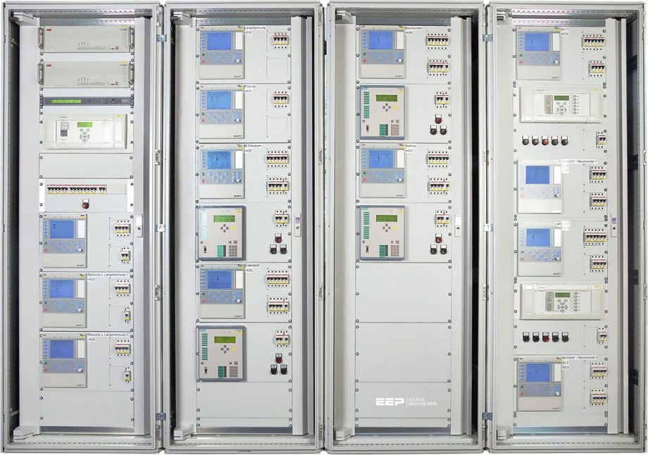 Earth fault protection in a solidly (effectively) earthed high voltage power systems (photo credit: ohb-system.de)
Effectively Earthed Systems
In the effectively earthed systems all transformers are normally connected to earth and will thus feed earth fault current to the fault. The contribution from all earthing locations gives special requirements for the protection system.
- Fault Resistance and Fault Current Levels
- Neutral Point Voltages
- Restricted Earth Fault Protection (REF)
- Logaritmic Inverse Relay
- Directional Comparison Schemes
- Inrush Current Stabilization
1. Fault Resistance and Fault Current Levels
In order to calculate fault currents in an effectively earthed system we must use the representation with symmetrical components. The symmetrical component scheme for a 132 kV system with a fault according to Figure 1 is shown in Figure 2.
The distribution of fault currents, from the different system earthing points, can be derived from the distribution in the zero sequence network (see Figure 2 below). By inserting varying fault resistances one can get the fault current level.
The fault resistance Rf, consists of the arc resistance and the tower foot resistance. The arc resistance is calculated by the formula:
Rarc = 28700×a / If1.4 (according to Warrington)
where a, is the arc length in meter, normally the insulator length, and If is the fault current in A.
A calculation will show that values will differs from below 1 Ω for heavy faults, up to 50-400 Ω for high resistive earth faults. The tower foot resistance depends on the earthing effectiveness of the towers, whether top lines are used etc.
For the tower foot resistance values from below 10 Ω up to 50 Ω have been documented.
2. Neutral Point Voltages
The occurring neutral point voltage, at different locations, can be seen in Figure 2. The designate U0, represents the neutral point voltage (3U0 = UN). It’s to be noted that U0 is generated by the earth fault current I0 through the zero sequence source. This implies that the angle between U0 and I0 is always equal to the zero sequence source angle, independent of the fault resistance and the angle between the faulty phase voltage and the line current in the faulty phase.
It must also be noted that UN will be very low when sensitive earth fault relays are used in a strong network with low zero sequence source impedances.
In an open delta secondary circuit there is a voltage also during normal service due to unbalances in the network. The voltage is mainly of third harmonic and of size 0,2-0,5% with conventional VTs and 1-3% together with CVTs.
This means that the sensitive directional earth fault protection must be provided with a third harmonic filter when used together with CVTs. The filtering must be quite heavy to ensure correct directional measuring for 1% fundamental content also with third harmonic contents of say 3%.
Recommended reading:
Essential fundamentals of harmonics distortion for future power quality experts
3. Restricted Earth Fault Protection (REF)
For solidly earthed systems a restricted earth fault protection is often provided as a complement to the normal transformer differential relay. The advantage with the restricted earth fault relays is their high sensitivity. Sensitivities of 2-8% can be achieved.
The level is dependent of the current transformers magnetizing currents whereas the normal differential relay will have sensitivities of 20-40%.
The connection of a restricted earth fault relay is shown in Figure 3. It is connected across each transformer winding in the figure.

It is quite common to connect the Restricted earth fault relay in the same current circuit as the transformer differential relay. This will due to the differences in measuring principle limit the differential relays possibility to detect earth faults. Such faults are detected by the REF.
The mixed connection is shown in the low voltage winding of the transformer, see Figure 3 above. The common principle for Restricted earth fault relays is the high impedance principle, see Figure 4.

The relay provides a high impedance to the current. The current will, for through loads and through faults, circulate in the current transformer circuits, not go through the relay. For a through fault one current transformer might saturate when the other still will feed current. For such a case a voltage can be achieved across the relay.
The calculations are made with the worst situations in mind and an operating voltage UR is calculated:
UR ≥ IFmax (Rct + Rl)
where,
- IFmax is the maximum through fault current at the secondary side,
- Rct is the current transformer secondary resistance and
- Rl is the loop resistance of the circuit.
Due to the fast saturation very high top voltages can be achieved. To prevent the risk of flashover in the circuit, a voltage limiter must be included. The voltage limiter can be either of type surge arrester or voltage dependent resistor.
The relay sensitivity is decided by the total current in the circuit according to the formula:
Ip ≥ n (IR + Ires + ∑Imag)
where,
- n is the CT ratio,
- IR is the current through the relay,
- Ires is the current through the voltage limiter and
- ∑Imag is the sum of the magnetizing currents from all CT’s in the circuit (normally 4).
It should be remembered that the vectorial sum of the currents must be used. The current measurement have to be DC insensitive to allow a use of AC components of the fault current in the calculations.
4. Logaritmic Inverse Relay
Detection of earth fault and back-up tripping with maintained selectivity in a solidly (effectively) earthed system is rather complicated due to the infeed of fault current from different direction concerning all faults.
A special inverse characteristic with a logaritmic curve has been developed to be suitable for these applications. The principle for earth fault relays in a effectively earthed system is shown in Figure 5 and the logaritmic inverse characteristic is shown in Figure 6.
The inverse characteristic is selected so that if the current of the largest infeed is less than 80% of the faulty objects current selectivity is achieved.

To enable use together with distance protection giving single-phase tripping a definite minimum time is set (normally 0.3 sec.). This ensures that a single phase tripping for heavy single phase faults can be done by distance protection relay first.
5. Directional Comparison Schemes
To provide detection of high resistance earth faults in an effectively earthed network it’s common to use a directional comparison scheme with directional earth fault relays at both ends of the power line. The relays at the two ends are directed towards each other and a communication between the relays, through a power line carrier (PLC) or a radio link, is introduced.
5.1 Principle For Communication Schemes
Communication can be made according to two main principles:
- Permissive scheme
- Blocking scheme
In a permissive scheme the directional earth fault relays will send a carrier signal (CS) to the remote end at detection of a forward fault. At reception of a signal and detection of a forward fault at the receiving end, an instantaneous trip is given. Normally the same situation occurs at both ends.
A permissive scheme principle is shown in Figure 7.

In a blocking scheme the directional earth fault relays are provided with a reverse locking element as a complement to the forward element. The reversed element is set to be more sensitive than the forward element and will, when a reverse fault is detected, send a carrier signal (CS), to the remote end.
At the remote end the forward element is provided with a short time delay T0 normally set to 50-150 ms, to check if a blocking signal is received. If not, the relay will trip. The same situation will for internal faults occur at both line ends. The principle of a blocking scheme is shown in Figure 8.
In most cases the Directional earth fault relays in a communication scheme also includes a communication independent back-up tripping with a time delay. Inverse or definite time delay can be used.
Normally the inverse characteristic and the logaritmic inverse characteristic gives the best possibility to achieve time selectivity also at back-up tripping.
5.2 Single Phase Tripping
When Distance protection relays with single phase tripping and auto reclosing are used at the same line as a scheme with earth fault relays it must be ensured that the distance protection relays are allowed to give their single-phase tripping first. Earth fault relays must therefore be time delayed to allow this. This is also valid when communication schemes are used.
During a single phase trip an unbalance in the complete network occurs and an earth fault currents flows through the network. These currents reaches levels up to 20% of the load current and an unnecessary tripping from earth fault relays can therefor be achieved.
The earth fault relays are normally blocked during the single phase auto reclose cycle.
5.3 Current Reversal
A special application problem occurs together with directional earth fault schemes communicating in a permissive overreaching (POR) scheme. The problem is fault current reversal which occurs when the CB at one end of the faulty line trips before the breaker at the other end.
The fault current changes direction in the parallel line and a timing problem to prevent maloperation at the end with a carrier signal (CS) receipt at the original fault occurring will occur (see Figure 9).

A special logic according to Figure 10 is required to prevent a unneccesary function.
5.4 Weak-End Infeed
In special applications, a situation where the fault current infeed from one end isn’t ensured during certain service conditions. A special weak end infeed logic can be used together with POR schemes. It is based on occurring zero sequence voltage and the receipt of a carrier signal (CS) from the remote (strong) end.
The logic for an earth fault weak-end infeed function includes a check of occurring UN voltage at carrier receipt and the breaker is tripped even if no operation of directional earth fault (DEF) relay is achieved due to a to weak source. It is also necessary to ‘mirror’ the Carrier signal back so the signal is sent back on receipt if the UN voltage is low, or if the circuit breaker is open.
Recommended reading:
Power line carrier channel (PLCC) and application of transmission line relaying
6. Inrush Current Stabilization
In some countries a second harmonic stabilization is required for sensitive earth fault relays. The background to this is that the inrush currents occurring at transformer energizing which, in some networks has long durations. The long durations are often achieved in weak networks. The second harmonic stabilization can then block the earth fault relay, during the inrush and prevent the risk of an unnecessary operation.
For inverse time delayed scheme a time setting is selected to achieve selectivity to instantaneous protection. This gives a long delay compared to normal inrush times and the inverse characteristic will then match the decay of the inrush current and keep the relay away from unwanted functions.
The only time when a stabilization is necessary is when very sensitive definite time delayed relays are used. In such cases the inrush can cross the corner with minimum current before the time elapses and an unwanted function can occur.
Recommended reading:
Protection coordination practices in distribution systems with distributed generation
Source: Protection application by ABB
Related electrical guides & articles


Edvard Csanyi
Hi, I'm an electrical engineer, programmer and founder of EEP - Electrical Engineering Portal. I worked twelve years at Schneider Electric in the position of technical support for low- and medium-voltage projects and the design of busbar trunking systems.I'm highly specialized in the design of LV/MV switchgear and low-voltage, high-power busbar trunking (<6300A) in substations, commercial buildings and industry facilities. I'm also a professional in AutoCAD programming.
Profile: Edvard Csanyi

Very Important
earth fault protection is of main isolate in a network 6,10kV
Very refreshing articles. I will like to keep them for reference purposes. How do I save them in a folder