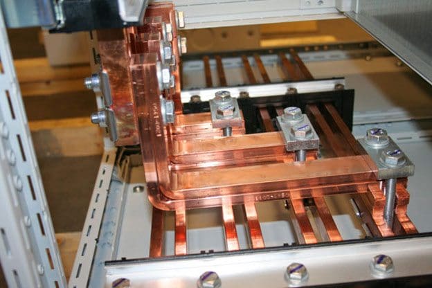
Busbars made up of flat bars
The construction of busbar is usually carried out by putting together several flat bars in parallel for each phase. The spacing between the bars is made equal to their thickness for practical reasons, and this leads to skin and proximity effects.
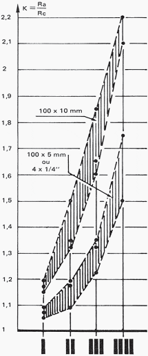
If one refers to published results, no accurate quantitative estimations of these combined effects can be found. An order of magnitude forthe extra loss coefficient K is given in figure 1 for 2 cross-sections of copper: 100 x 5 and 100 x 10 mm.
For each group of 1, 2, 3 or 4 bars, points corresponding to published results encircle a shaded area in which the probable value of K must be situated. In the absence of any more accurate results, the search for a value of K for a set of bars of any size can be made using the curves of figure 1, and equating the set to a single bar of the same height but of a width equal to the overall width of the whole set. The resistance Rc is the equivalent to that of all the bars in parallel.
The coefficient K is here found by excess, but this extrapolation is only valid for bars which are not separated by more than their thickness.
In effect, a generous spacing and a judicious positioning of the bars lead to a reduction in the loss coefficient; for example in figure 2 are shown the coefficients K for groups of 3, 4, 6 and 8 bars of 100 x 6 mm; the closest bars are 6 mm apart, the furthest 60 mm. The relative gain on the losses is 20% for 3 bars and 40% for 4 bars, according as to whether they are in one or two batches. It is rare that the use of 5 bars grouped together is considered because of the high loss coefficient caused by inadequate use of the central bar.
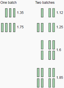
It has also been proposed to place the 4 bars of a phase along the edges of a square, a solution which gives the advantages of a tubular conductor, but the supports and the tappings become fairly complicated here. All these indications concern the skin effect acting simultaneously with the proximity effect, in a group of several bars of the same phase; for 3 phases, if the distance between the closest bars of 2 different phases is less than twice the height of these bars, an inverse proximity effect acts in addition to the two previous effects.
In order to obtain a value for the coefficient K giving the increase in the corresponding losses, one should refer to the DIN standards no. 43.671 [23] which give the coefficient K4 for bars of 5 or 10 mm thickness, or to reference [24] in which the average geometric distances of various shapes of conductor make it possible to carry out the relevant calculation.
An arrangement which is of particular interest in the case of 3 phase system is the so-called sandwich: busbars inter twined or permuted. The bars of each of the phases are not placed in independent groups for each phase, but are on the contrary placed in between each other.
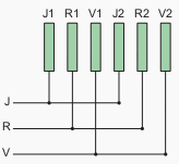
A busbar having 2 bars per phase (J, R, V) is thus arranged as in figure 3 ; the proximity effects are eliminated, the current density in each bar is almost identical and the coefficient K is little over 1.
Two disadvantages limit the general use of this process: certain complications in the connection and joints, and the difficulty of obtaining isolation of the phases, even at low voltages.
An additional advantage is the reduction in the electrodynamic stresses, to which can be added a decrease in the inductance per phase by a factor of 10; this last characteristic of sandwich type busbars has a favorable effect on the induced voltage drop in normal operation, but leads to an increase in the value of short-circuit current.
Minimal heating, or reduction in the extra losses?
Up till now the effects mentioned have only been analysed from the point of view of the increase in the effective A.C. resistance, that is of the extra losses produced by the Joule effect.
The normal consequence is increased heating of the conductors, but this is sometimes compensated for by adopting an arrangement which favors cooling by radiation or convection. Now the heating is at present time the only important criterion taken into consideration for the designing of a high current conductor; however the minimal heating is not always found in conjunction with the lowest loss coefficient; it can be seen from figure 15 that the coefficient K is more or less the same for one 100 x 10 bar or two 100 x 5 bars, but because of the larger cooling surface in the latter case, it is possible, at equivalent heatings, to obtain a current of 10% greater, and thus losses which are 20% greater.
Another characteristic example is the tubular conductor whose optimized shape guarantees a coefficient K close to 1; however this tube has the smallest cooling surface (without any forced ventilation on the inside) and it can be seen in Figure 4 that it is far from having the profile which carries the highest current, for a heating and a cross-section the same as other configurations.

The designer of a high current conductor will sometimes be advised to choose a technology not only according to the heating produced, but also according to the total losses.
Resistivity of the metal, copper or aluminium?
It was assumed in what has preceded that the metal used was copper; it now should be noted that the skin and proximity effects become more marked as the resistance decreases.
A copper conductor will thus have a higher loss coefficient than the same conductor made of aluminium, but the latter, requiring a cross-section 1.6 times greater to obtain the same resistance (for a direct current), losses this advantage over the copper conductor because the two conductors have the same coefficient K for the same shape and the same resistance Rc.
In practice, the replacement of copper by aluminium is not done on the basis of equivalent resistance or voltage drop but rather on that of equivalent heating; this amounts to multiplying the cross-section by 1.4 to 1.5 only, in order to take into account the improved cooling of the larger surface.
The price per kilo and the much lower density of aluminium are the determining factors which lead to the metal being chosen to high current intensity conductors.
Influence of the frequency
Only the industrial frequency of 50 Hz has been taken into consideration in the preceding calculations; their accuracy which is only relative however makes them valid for frequencies of up to 60 Hz. Extra loss coefficient for the skin effect in cylindrical conductors (tubes and flat rods) at 50 or 60 Hz can be used for any other frequency with the corrections given.
Amongst these frequencies 25 Hz is hardly ever used; as for 16 2/3 Hz it can be assimilated to direct current. Serious problems of skin effect are set by the 400 Hz frequency which is used for special circuits (marine, aviation, etc.), as soon as the current reaches a few hundred amperes: the “skin ” of the copper is reduced to 3 mm at this frequency.
In industrial networks, harmonic currents having frequencies which are multiples of 50 Hz (the harmonics 3 and 11 cause the most nuisance) can be superposed to the fundamental frequency. These currents encounter an effectively increased resistance and significant losses and heating occur.
Copyright Notice
This technical article is protected by U.S. and international copyright laws. Reproduction and distribution of PDF version of this technical article to websites such as Linkedin, Scribd, Facebook and others without written permission of the sponsor is illegal and strictly prohibited.© EEP-Electrical Engineering Portal.
Related electrical guides & articles
Premium Membership
Edvard Csanyi
Hi, I'm an electrical engineer, programmer and founder of EEP - Electrical Engineering Portal. I worked twelve years at Schneider Electric in the position of technical support for low- and medium-voltage projects and the design of busbar trunking systems.I'm highly specialized in the design of LV/MV switchgear and low-voltage, high-power busbar trunking (<6300A) in substations, commercial buildings and industry facilities. I'm also a professional in AutoCAD programming.
Profile: Edvard Csanyi




Sir, we intend to manufacture compact sandwich busducts & type tested LV switchboards in our manufacturing facility. Are there any consultants or standards which can be utilized for product design in this segment.
I need insulated copper busbar to combine 2000A/600VDC current – positive and negative separately
please give us some details of LOW VOLTAGE,HIGH CURRENT DC COPPER BUS BAR DESIGN IN COPPER INDUSTRIES, DC BUS CONDUCTOR SIZING,SINGLE BUS,MULTI BUS BAR, CURRENT AMPERAGE SELECTION ( AS WE DO NOT FIND ANY AMPERE RATING CHARTS MORE THAN 8000A-9000A AND IEC STANDARDS,),RECOMMEDED RECTIFIER OUTPUT LEADS, CONNECTION ACCESSORIES- DC FLEXIBLE LINKS, HEAT LOSSES,RADIATION LOSSES.SKIN EFFECT.,SUPPORT INSULATORS FOR DC BUSSES.
will be happy to get the newsletter
Dear Edward,
Good Day to You.
In low voltage switch gear panel time of construction Bus bar joints can I used copper bushes instead of bus bar bending. Please kindly advise me
Regards,
sasikumar.B