Electromagnetic Stresses
When a conductor carries a current it creates a magnetic field which interacts with any other magnetic field present to produce a force. When the currents flowing in two adjacent conductors are in the same direction the force is one of attraction, and when the currents are in opposite directions a repulsive force is produced.

In most busbar systems the current-carrying conductors are usually straight and parallel to one another.
Normally in most busbar systems the forces are very small and can be neglected, but under short-circuit conditions, they become large and must be taken into account together with the conductor material fibre stresses when designing the conductor insulator and its associated supports to ensure adequate safety factors.
The factors to be taken into account may be summarised as follows:
- Stresses due to direct lateral attractive and repulsive forces.
- Vibrational stresses.
- Longitudinal stresses resulting from lateral deflection.
- Twisting moments due to lateral deflection.
In most cases the forces due to short-circuits are applied very suddenly. Direct currents give rise to unidirectional forces while alternating currents produce vibrational forces.
Maximum stresses
When a busbar system is running normally the interphase forces are normally very small with the static weight of the busbars being the dominant component.
Under short-circuit conditions this is very often not the case as the current rises to a peak of some thirty times its normal value, falling after a few cycles to ten times its initial value.
These high transitory currents create large mechanical forces not only in the busbars themselves but also in their supporting system.
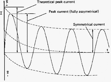
The peak or fully asymmetrical short circuit current is dependent on the power factor (cos φ) of the busbar system and its associated connected electrical plant. The value is obtained by multiplying the r.m.s. symmetrical current by the appropriate factor given in Balanced three-phase short-circuit stresses.
If the power factor of the system is not known then a factor of 2.55 will normally be close to the actual system value especially where generation is concerned. Note that the theoretical maximum for this factor is 2√2 or 2.828 where cos φ=0.
These peak values reduce exponentially and after approximately 10 cycles the factor falls to 1.0, i.e., the symmetrical r.m.s. short circuit current.
The peak forces therefore normally occur in the first two cycles (0.04 s) as shown in Figure 1 below.

In the case of a completely asymmetrical current wave, the forces will be applied with a frequency equal to that of the supply frequency and with a double frequency as the wave becomes symmetrical. Therefore in the case of a 50 Hz supply these forces have frequencies of 50 or 100 Hz.
The maximum stresses to which a bus structure is likely to be subjected would occur during a short-circuit on a single-phase busbar system in which the line short-circuit currents are displaced by 180°.
In a balanced three-phase short-circuit, the resultant forces on any one of the three phases is less than in the single-phase case and is dependent on the relative physical positions of the three phases.
In the case of a single-phase short-circuit, the forces produced are unidirectional and are therefore more severe than those due to a three-phase short-circuit, which alternate in direction. The short-circuit forces have to be absorbed first by the conductor. The conductor therefore must have an adequate proof strength to carry these forces without permanent distortion.
Copper satisfies this requirement as it has high strength compared with other conductor materials (Table 2 below).
Table 2 – Typical relative properties of copper and aluminium
| Properties of Cu and Al | Copper(CW004A) | Aluminium (1350) | Units |
| Electrical conductivity (annealed) | 101 | 61 | % IACS |
| Electrical resistivity (annealed) | 1.72 | 2.83 | μΩ cm |
| Temperature coefficient of resistance(annealed) | 0.0039 | 0.004 | /° C |
| Thermal conductivity at 20°C | 397 | 230 | W/mK |
| Coefficient of expansion | 17 x 10–6 | 23 x 10–6 | /° C |
| Tensile strength (annealed) | 200 – 250 | 50 – 60 | N/mm2 |
| Tensile strength (half–hard) | 260 – 300 | 85 – 100 | N/mm2 |
| 0.2% proof stress (annealed) | 50 – 55 | 20 – 30 | N/mm2 |
| 0.2% proof stress (half–hard) | 170 – 200 | 60 – 65 | N/mm2 |
| Elastic modulu | 116 – 130 | 70 | kN/mm2 |
| Specific heat | 385 | 900 | J/kg K |
| Density | 8.91 | 2.70 | g/cm3 |
| Melting point | 1083 | 660 | °C |
Because of the high strength of copper, the insulators can be more widely spaced than is possible with lower-strength materials.
Methods of reducing conductor stresses
In cases where there is a likelihood of vibration at normal currents or when subjected to short- circuit forces causing damage to the conductor, the following can he used to reduce or eliminate the effect:
a) Reduce the span between insulator supports.
This method can be used to reduce the effects of both continuous vibration and that due to short-circuit forces.
b) Increase the span between insulator supports.
This method can only be used to reduce the effects of vibration resulting from a continuous current. It will increase the stresses due to a short-circuit current.
c) Increase or decrease the flexibility of the conductor supports.
This method will reduce the effects of vibration due to continuous current but has very little effect on that due to short-circuit forces.
d) Increase the conductor flexibility.
This can only be used to reduce the effects of vibration due to a continuous current. The short-circuit effect is increased.
e) Decrease the conductor flexibility.
This method will reduce the effects of vibration due to either a continuous current or a short-circuit.
It will be noted that in carrying out the various suggestions above, changes can only be made within the overall design requirements of the busbar system.
Reference: Fundamentals of Power System Protection
Copyright Notice
This technical article is protected by U.S. and international copyright laws. Reproduction and distribution of PDF version of this technical article to websites such as Linkedin, Scribd, Facebook and others without written permission of the sponsor is illegal and strictly prohibited.© EEP-Electrical Engineering Portal.
Related electrical guides & articles
Premium Membership
Edvard Csanyi
Hi, I'm an electrical engineer, programmer and founder of EEP - Electrical Engineering Portal. I worked twelve years at Schneider Electric in the position of technical support for low- and medium-voltage projects and the design of busbar trunking systems.I'm highly specialized in the design of LV/MV switchgear and low-voltage, high-power busbar trunking (<6300A) in substations, commercial buildings and industry facilities. I'm also a professional in AutoCAD programming.
Profile: Edvard Csanyi


I wish to have some knowledge on thermal imaging of the switchboard.
Sir,I want to know if the busbars are already under mechanical stresses ,is it affect the conductivity of the busbar
Hi Sir.
Im still waiting for your reply please.
Hi Sir Engineer.
Thanks for your lovely topics…Its really interesting….I just want your opinion on what sofware you recomend to use in desining the installation wiring which can save the time and effort of engineers and installation designers….provided that the software can be used or comply with AS/NZ STANDARED employed in Australia and Newsland.
Many thanks with best regards.
Hussain
Elect.Eng.
What do you consider by desining the installation? Voltage level? Electrical design, or control or protection wiring schemes… or maybe just the design of outlets and lighting?
Make your question a little bit more clearer ;) There are many aspects of electrical design.
one 500kva 11kv/430v transformer got damaged earlier at site. After check delta connection on hv side was found open which was reconnected and after putting load on it, it stood ok for some 15 hours and again delta connection got open with burning of ht fuses. Again it was repaired and same thing happened. what could be the problem? load side ok.
Sir,i want to know about details of lighting transformer.please
Lighting transformer is used for lighting bulbs that require reduced voltage. If you ask me, there is nothing special about them that differs from other transformers. However, you can read more about this topic in category ‘Lighting’ here:
https://electrical-engineering-portal.com/category/lighting
Kind regrds
Lighting transformers are basically the same as of power transformer however this type of transformers provides the power for normal illumination circuit.This type of transformer is used in the power system as the lighting loads are normally inductive in nature that may affect the Voltage current current curve of a power system,hence in order to correct this a lighting transformer is used in circuit that basically act as an Isolation Transformer in circuit.