
Immediate cut off the electrical power
As their name indicates, emergency operations are intended to eliminate, as quickly as possible, a danger that occurs unexpectedly. The emergency break is designed to cut off the electrical power, whereas the emergency stop takes account of the danger of mechanical movements.
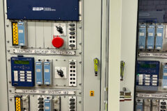
 Emergency breaking, stop and isolation intended to eliminate danger as quickly as possible (on photo: Control panel of the automatic production line)
Let’s discuss three main emergency operations used in industrial applications:
1. Emergency Breaking
Emergency breaking is normally required for all installations in which there may be faults or risks of electric shocks: laboratories, boiler rooms, kitchens, illuminated signs, pumping of flammable liquids, test platforms, etc. It must break all live conductors (including neutral, but not pe or pen).
This must be possible on load and in a single operation.
Standard IEC 60364-5-53 defines the conditions for emergency breaking. Specific regulations can extend its application to other circuits. In principle, the emergency breaking device should be located on or near the devices(s) to be broken, and be easily identifiable (by operating or emergency staff).
On/off functional control devices (such as switches, contactors, circuit breakers) can be used for emergency breaking if they meet the above requirements. It should be noted that in this case, the breaking of single-phase (Ph+N) terminal circuits is possible with a single-pole device. This provision applies in particular to lighting circuits.
Caution: if the door of the board concerned is closed and locked with a key, a separate mechanical control or an external electrical control is necessary.
In installations in non-industrial or commercial premises, offices (or similar, measuring less than 500 m2), the main control and protection device at the origin of the installation may be used for emergency breaking, if it is easily accessible.
If there is a need for proximity of the device (in view of the dangers) and inaccessibility is required under normal conditions, emergency breaking must be via a “glass break” device with either direct control (pushbutton) or key release.
For the safety of machinery, the emergency stop is defined by standard IEC 60204-1.
Figure 1 – Red button on a yellow background of an emergency stop

For certain areas or equipment (boiler rooms, cooking equipment, large kitchens, illuminated signs, etc.) the emergency breaking must be:
- Either positive safety type (undervoltage release coils), or
- Accompanied by indication of the open/closed state (indicators, etc.) showing the position of the breaking device.
It should be noted that separate lighting devices/other circuits may also be required (for example, in boiler rooms).
The requirements relating to emergency breaking, functional control, emergency stops and isolation are described in standard IEC 60364-5-53.
Figure 2 – Mushroom head unit with the key unlocking

It must be possible to use emergency breaking methods, other than the emergency stop, to eliminate an unexpected danger. Examples of this include ventilation or pumping systems, neon signs, certain important buildings, laboratories, boiler rooms, large kitchens, etc.
The notions of positive safety (use of undervoltage releases) and locking in breaking position are required for these uses, as well as the use of clearly identified devices (red on a contrasting background).
However, these devices are not necessary for terminal circuits that do not present any particular danger: heating, lighting, power sockets.
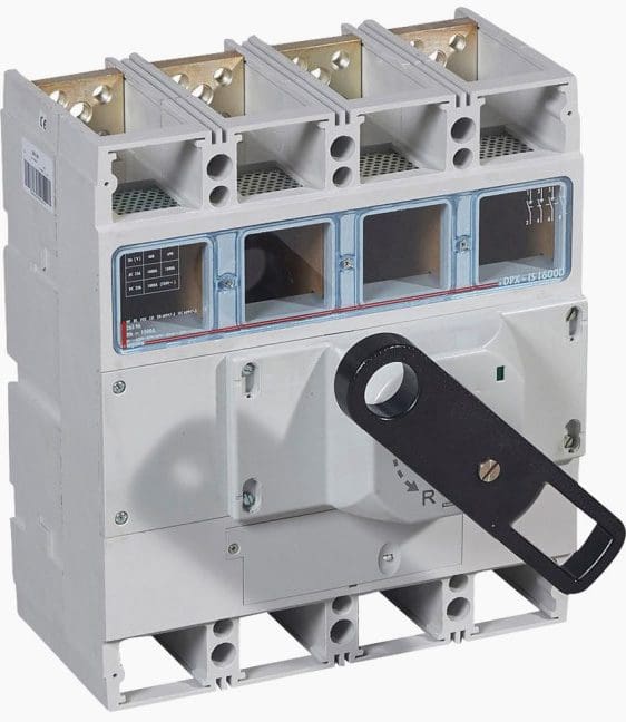
Figure 3 – Isolating switch 4P 1000 A with front handle (Legrand)
Go back to the Contents Table ↑
1.1 Examples of emergency breaking schematics
Figure 4 – Motor-driven control of a circuit breaker with emergency breaking by the off button OFF and shunt coil. manual reset.

Figure 5 – Direct control of a circuit breaker. Emergency breaking is carried out by the OFF button EB and the shunt coil SC.
Figure 6 – Motor-driven control for a circuit breaker with reset by the external handle. Opening by undervoltage release.
Figure 7 – Wiring of motor-driven control for circuit breakers. The OFF button off can be used for emergency breaking.
Where:
- AC – auxiliary contact
- FS – fault signal contact
- SC – shunt coil
- UC – undervoltage coil
- EB – emergency breaking
- ON – On button
- OFF – Off button
- R – reset
Go back to the Contents Table ↑
2. The emergency stop
When movements produced by electrical devices or machines can be the source of danger, these devices or machines must be equipped with emergency stop device(s) located as close as possible to the users. Emergency stops are required for example for escalators, lifts and elevators, cranes and transporters, electrically controlled doors, car washes, etc. and of course for machines: mechanical kneading machines, handling robots, and machine tools in the broadest sense.
Each machine must be fitted with one or more emergency stop devices, which are clearly identifiable, accessible, in sufficient numbers, avoiding dangerous situations arising or continuing.
- If its presence does not reduce the risk
- If the stopping time is not shorter than the emergency break
- For portable machines and manually guided machines.
The emergency stop must be activated by as direct action as possible and with the notion of “positive safety”: direct action on the contacts opening the circuit or stop given priority in the event of a fault on the equipment or the power supply.
Suggested Course – Electrical On-Site Installations Course: Steps in Execution Stages
Electrical On-Site Installations Course: Steps in Execution Stages
Go back to the Contents Table ↑
2.1 Emergency stop for the safety of machinery
Control station with a yellow cover and red “push-turn” mushroom head button conforming to standard IEC 60204-1 (1/4 turn to unlock). Emergency stop devices must be provided for any part of an installation for which it may be necessary to control the power supply in order to eliminate an unexpected danger.
The emergency stop is intended to eliminate a danger, which does not necessarily have an electrical origin, as quickly as possible.
Figure 8 – Emergency stop control station with a Ø40mm turn to rest mushroom head

The mushroom head has a yellow ring that is only visible in the deactivated position giving a clear visual indication when activated.
Go back to the Contents Table ↑
2.2 Examples of emergency stop schematics
Figure 9 – Conventional layout of supply to a relay with switch-off priority
Figure 10 – Motor-driven control for a circuit breaker with automatic reset after closing of the circuit breaker. Opening by undervoltage coil.

Figure 11 – Direct on a circuit breaker by “mushroom head” button and undervoltage coil

Where:
- AC – auxiliary contact
- FS – fault signal contact
- UC – undervoltage coil
- ON – On button
- ES – emergency stop
It’s important to note that time-lag (800 ms) undervoltage releases prevent unwanted stopping in the event of micro-breaks.
Go back to the Contents Table ↑
3. Isolation
Isolation is used to separate an installation or part of an installation electrically. The purpose of isolation is to ensure the safety of people working on it. A breaking device providing the isolation function must be installed:
- at the origin of all installations
- at the origin of each circuit or group of circuits
The devices which carry out isolation may be isolators, isolating switches, circuit breakers, power sockets, fuse carriers, isolating blades, disconnect terminals or any device which provides a minimum contact opening distance of:
- 4 mm for 230/400 v voltage
- 8 mm for 400/690 v voltage
- 11 mm 1000 v voltage
For double break devices, the distances must be multiplied by 1.25.
Go back to the Contents Table ↑
3.1 Isolation with permanent contact indication
This characteristic is checked by reliable control between the position of the contacts and that of the control switch handle. the indication “I” or “O” (red or green) on the handle thus guarantees the actual contact position. Compliance with standard
IEC 60947-2 is evidence of this.
Caution! – Isolation does not on its own ensure that the installation is made safe. Appropriate methods must be employed to prevent any unwanted re-energising (padlocking, signs, locked rooms, earthing) and lockout the installation.
Requirements concerning isolation are also applicable to machines and work equipment that have to be isolated from their power source(s) in order to carry out adjustment operations or maintenance work.
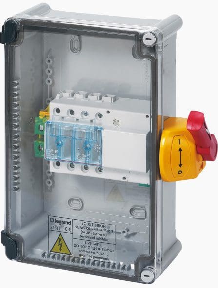
Full load switch units carry out both emergency breaking and isolation.
Figure 12 – Full load switch unit with Vistop, 63A, 3P (Legrand)
Go back to the Contents Table ↑
3.2 Isolation with visible contact indication
The actual position of the separate contacts is directly visible. visible contact indication can be obtained by means of a display window or by using a plug-in or draw-out device.
It is important to clearly identify the local requirements concerning isolation. For example, in France, visible contact indication is required for subscriber stations whose power does not exceed 1250 kVA, supplied by a single transformer with Lv metering.
It is also required upstream of the supply point for monitored power connections.
Figure 13 – Visible contact indication obtained by means of a display window

Other important definitions:
Protective breaking
Breaking associated with a protective function (overcurrents, residual current fault, overvoltage, etc.).
Functional control
Control of operation (on, off, variation) for solely functional purposes: thermostats, dimmers and remote control switches are examples of this. Power sockets > 32 A cannot perform functional control of a device.
They must be combined with a load breaking device.
Breaking for mechanical maintenance
Breaking solely intended to avoid mechanical risks (movement) during non-electrical work. if they only have this function, they cannot be used for emergency breaking purposes.
Suggested Course: Overcurrent Protection Course: Principles, Relays, Schematics & Settings
Overcurrent Protection Course: Principles, Relays, Schematics and Settings
Go back to the Contents Table ↑
Source: Legrand
Related electrical guides & articles


Edvard Csanyi
Hi, I'm an electrical engineer, programmer and founder of EEP - Electrical Engineering Portal. I worked twelve years at Schneider Electric in the position of technical support for low- and medium-voltage projects and the design of busbar trunking systems.I'm highly specialized in the design of LV/MV switchgear and low-voltage, high-power busbar trunking (<6300A) in substations, commercial buildings and industry facilities. I'm also a professional in AutoCAD programming.
Profile: Edvard Csanyi

Hi Edvard
How are you
I am your follower from 10 years
I want to write some articles on your portal
Hi Surinder, please submit your application here:
https://electrical-engineering-portal.com/technical-articles/job-hv-electrical-engineer
We are always looking for an experienced electrical engineer with writing skills to join our team for writing in fields of HV in general, high- medium- or low-voltage applications, protection relaying, power plant engineering, equipment testing and commissioning including theory, applications and experience in related fields.