
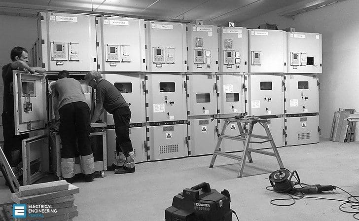
Erection of medium voltage (MV) switchgear
Before commencing erection of medium voltage (MV) switchgear check that all connections are tight on busbars and on main and auxiliary circuits. Examine the insulation carefully, because there have been cases of burned out connections due to failure to observe this precaution.
Obvious faults such as distorted panel work, broken meter glass and damaged packing cases should be noted and immediate steps taken to rectify the damage or to return the switchgear to the supplier.
After erection, steps must be taken to prevent deterioration of the switchgear due to damp, dust or casual damage. Substations should be cleared out and locked fast and should not be used as a site office, store or workshop after the switchgear has been installed.
When all erection and jointing work is complete the medium voltage switchgear must be inspected and thoroughly cleaned to remove cuttings of cable, spare nuts, washers, accumulations of dust or copper filings and tools which may have been left behind.
However, it is dangerous to blow out equipment because dust, filings, light metal scraps, rags and sawdust can be blown into positions where they become inaccessible and may pass unnoticed.
It is better to clean manually and vacuum the plant.
In the erection of the switchgear the following points should be emphasised.
Where steel channels are used as foundations, ensure that they are correctly laid to an accuracy of about ±1 mm in 3 m. Use a masking strip to prevent fouling by the floor materials. Read and apply the manufacturer’s erection instructions and use the correct tools such as torque spanners to obtain the appropriate tightness of nuts. Make sure switchgear is properly aligned.
This means vertically and horizontally in both longitudinal and lateral directions.
When the floor is being laid and there are no steel inset channels, it should be level both front to back and should not vary by more than a millimetre or so between cubicle centres. When the floor is being laid it is common practice to form pockets at the foundation hole positions in order to avoid having to cut them out of the solid floor at installation time.
The floor should be marked out in accordance with the switchgear assembly drawings usually provided by the manufacturer to ensure that the switchgear is correctly located with respect to cable trenches, building walls and other equipment in the room.
A datum line requires to be established usually along the rear foundation bolts, and using normal geometric methods the switchboard and foundation bolt holes can be located. The method of positioning the switchgear is dependent on a number of factors such as switchgear size, building location, site accessibility and lifting tackle available.
Lifting eyes are often either incorporated into switchboards or can be screwed into pre-machined holes, but generally slinging is necessary and this should be done strictly in accordance with the manufacturer’s recommendations.
Without the use of cranes, however, the traditional manual methods utilising jacks and roller bars are effective.
Care must be taken not to exert pressure on weak parts such as control handles during this manhandling. Positioning of the cubicles should start near to the centre of the switchboard, installing as early as possible the enclosures associated with any special chambers or trunking.
The first enclosure should be positioned and checked to ensure the side sheets are plumb and that any runner rails are level in both planes. When the first enclosure panel is correctly set the remaining enclosures should be positioned successively on alternate sides of this panel to make the front form an unbroken line.
Adjacent enclosures should be bolted together after they have been correctly aligned using whatever shimming proves necessary to make sure that the cubicles are vertically and horizontally true. The fixing bolts should be positioned in the foundation holes and cemented in leaving adequate time for the cement to set before tightening up.
Checking of cable and other connections

A further examination of all incoming and outgoing circuit and auxiliary cables, including a test of the correctness of the connections at the remote ends, should be done; this should include measuring the insulation resistance and continuity of all cables and wiring including internal and auxiliary connections.
Where appropriate, phase rotation checks must be made before three-phase drives are energised. All moving parts must be inspected to ensure they are all operative. Dashpots must be filled to the correct level with the right grade of fluid, and the operation and accuracy of meters and relays by secondary or primary injection tests should be checked.
All cable boxes must be properly topped up and compound filling spouts capped off. All insulators and spouts must be clean and dry and cover plates securely bolted up with all screws in position and tightened and breather vents clear of obstruction. Ensure that the top of the switchgear is free from all dirt and rubbish.
A final check on all incoming and outgoing cable connections to terminals ensures that they are tight and have adequate clearance. High voltage testing can then be carried out to the test figures laid down in the appropriate BS switchgear specification or as specified by the client’s engineers who should witness the tests and sign the test results.
After testing, precautions must be taken to discharge any static and remove the test connections before bolting up any covers removed for testing. Before energising, the operation of all circuit breakers and relays should be confirmed manually and electrically to ensure that no sticking or malfunction is present, particular attention being given to manual trip and close operations and to the operation of overcurrent relays and residual current devices.
Going Alive
When the switchgear is ready to make alive all circuits not in service shall be locked off at each end and safety operation procedures adopted.
All switching operations should be carried out by a competent person.
1 The substation’s entry and emergency exist doors must be operative and kept clear and free from obstruction.
2 All substations should be kept locked when the switchgear is live, and access restricted to authorised personnel only.
3 Danger, safety, shock cards and any statutory notices must be prominently displayed.
4 Tools required for operating switchgear should be stored adjacent to the equipment in proper racks or cabinets.
5 Circuit and interlock keys should also be contained in special cabinets under the control of authorised personnel and no spare keys must be allowed to abort the safety of the system.
6 Batteries should be examined to ensure that they have received their first charge and the electrolyte is at the correct level and of appropriate specific gravity.
7 The fire-fighting requirement should be checked and if it is CO2 it must be confirmed that the safety lock-off procedure is understood by the personnel authorised to enter the substation.
8 External warning notices must be fixed to protect any strangers from inadvertently suffocating.
Reference: Geoffrey Stokes – Handbook of electrical practice
Related electrical guides & articles


Edvard Csanyi
Hi, I'm an electrical engineer, programmer and founder of EEP - Electrical Engineering Portal. I worked twelve years at Schneider Electric in the position of technical support for low- and medium-voltage projects and the design of busbar trunking systems.I'm highly specialized in the design of LV/MV switchgear and low-voltage, high-power busbar trunking (<6300A) in substations, commercial buildings and industry facilities. I'm also a professional in AutoCAD programming.
Profile: Edvard Csanyi

Dear sir,
I would like to join a switchgear manufacturing company as a purchase manager. I have been working in the gears & gear boxes manufacturing field for the past 19 yrs as a purchase manager. I would like to know the components and the material of the components used in a switchgear, for me to attend a interview. I am a mechanical engineer.
Dear sir, may i have the reference or standar such as IEC,IEEE, etc, why “substation should be cleared out and locked fast and should not be used as a site office, store or workshop after the switchgear has been installed”? would you mind to share it to me. thank you
sir,
Your gesture of sharing your experiences in this way is highly appreciable. i am really getting a great benefit from this. Thanks