
Estimated Study Time: 9 minutes
Inputs for Coordination Calculation
A 440 V 60 Hz switchboard feeds a 4-wire distribution board for small loads such as socket outlets. The switchboard has a fault making capacity of 100kA rms. After applying diversity factors to the loads the total load current is 90 A. Moulded case circuit breakers (MCCBs) rated at 16 A and 32 A are to be used for the loads.
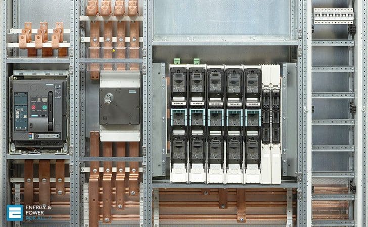 Example for Coordination of Cascaded Circuit Breakers (on photo: Low voltage SIEMENS SIKUS 1600 power distribution board; credit: DirectIndustry.com)
The installation will use cables having copper conductors and XLPE insulation. The cable from the switchboard to the distribution board is 20 metres in length.
A typical load cable is 15 metres in length and will carry a current of 29 A at a power factor of 0.85 lagging.
Ignore the presence of induction motors at the switchboard and find the following:
- Rating of the incoming circuit breaker.
- Size of the incoming cable.
- Size of the load cable.
- Check that the MCCB coordination is complete.
The following sequence will be used to calculate the results:
- Choose the upstream MCCB at the switchboard and its settings
- Choose the incoming feeder cable
- Choose the downstream load MCCB and its settings
- Find the upstream fault source impedance
- Find the cut-off, or let-through, current from the switchboard
- Find the impedance of the incoming cable
- Find the impedance of the load cable
- Find the fault current at the distribution board, point B
- Find the fault current at the beginning of the load cable, point C
- Find the fault current at the end of the load cable, point D
- Check the peak making capacity and peak let-through capacity of the MCCBs chosen above
- Find the highestI-squared-t value for the upstream MCCB
- Calculate a suitable size for the load cable to satisfy the I2t duty
- Calculate the volt-drop in the load cable
- Select the largest conductor size from the above calculations
- Plot the results (coordination curve)
Let’s dive into solution!
1. Choose the upstream MCCB at the switchboard and its settings
From a manufacturer’s data sheet a 125 A MCCB with an adjustable 100 A thermal release is chosen. The thermal release is set to 90 A to match the total load.
2. Choose the incoming feeder cable
From a manufacturer’s data sheet several cables can be compared for the same ambient conditions and laying arrangements. Their details are:
- 50 mm2 cable, maximum current 124 A, R = 0.492, X = 0.110 ohms/km.
- 70 mm2 cable, maximum current 159 A, R = 0.340, X = 0.106 ohms/km.
- 95 mm2 cable, maximum current 193 A, R = 0.247, X = 0.093 ohms/km.
3. Choose the downstream load MCCB and its settings
From a manufacturer’s data sheet a 32 A MCCB with an adjustable 32 A thermal release is chosen. The thermal release is set to 29 A to match its load.
4. Find the upstream fault source impedance
For a prospective symmetrical fault current of 100 kA rms the upstream fault source impedance Zup is:
5. Find the cut-off, or let-through, current from the switchboard
From a manufacturer’s data sheet a 125 A MCCB has a let-through current Ip of 25 kA peak for a prospective fault current Is of 100 kArms.
6. Find the impedance of the incoming cable
The impedance Zc1 of the incoming cable is:

7. Find the impedance of the load cable
The impedance Zc2 of the incoming cable is:
From a manufacturer’s data sheet several cables can be compared for the same ambient conditions and laying arrangements. Their details are:
- 6 mm2 cable, maximum current 33.8 A, R = 3.91, X = 0.130 ohms/km.
- 10 mm2 cable, maximum current 46.7 A, R = 2.31, X = 0.126 ohms/km.
The impedance Zc2 of the load cable is:

8. Find the fault current at the distribution board, point B
From a manufacturer’s data sheet the contact impedance data for low voltage MCCBs are:
| MCCB (Rating in Amps) | Resistance (in Ohms) | Reactanse (in Ohms at 60Hz) |
| 16 | 0.01 | neglect |
| 20 | 0.008 | neglect |
| 25 | 0.0065 | neglect |
| 32 | 0.005 | 0.000009 |
| 50 | 0.0027 | 0.000016 |
| 63 | 0.002 | 0.000025 |
| 80 | 0.0014 | 0.000042 |
| 100 | 0.0011 | 0.00007 |
| 125 | 0.0008 | 0.0001 |
| 160 | 0.00055 | 0.00015 |
| 200 | 0.0004 | 0.0002 |
| 250 | 0.00029 | 0.00027 |
| 320 | 0.0002 | 0.0004 |
Hence the upstream MCCB impedance Zm1 is 0.0008 + j 0.0001 ohms. Therefore the fault impedance Zfb is:
![]()
The fault making current Ifb is:
Where Vp is the line-to-neutral voltage. Locate the point R for 26,195 A on the prospective curve in Figure 1.
9. Find the fault current at the beginning of the load cable, point C
Hence the downstream MCCB impedance Zm2 is 0.005+j0.000009 ohms. Add this to Zfb to give the fault impedance Zfc as:

The fault making current Ifc is:
10. Find the fault current at the end of the load cable, point D

Add Zc2 to Zfc to give the fault impedance Zfd as:

The fault making current Ifd is:
11. Check the peak making capacity and peak let-through capacity of the MCCBs chosen above
The following manufacturer’s data are typical for 125 A and 32 A MCCBs:
| MCCB Rating | Making capacity | Let-through capacity kApeak (cut-off) | |
| kArms | kApeak | ||
| 32 A | 95 | 209 *** | 6.0 |
| 125 A | 132 | 290 *** | 25.0 |
*** Approximate values of the doubling factor taken to be 2.2
Hence the peak making capacity of the 32 A MCCB is well in excess of the let-through peak current of the 125 A MCCB.
12. Find the highest I2t value for the upstream MCCB
Locate two points P and Q on the curve of the upstream MCCB as follows,
| Point | Current in p.u. | Current in Amps | Time in seconds | I2t |
| P | 14 | 406 | 6 | 989016.0 |
| Q | 602 | 17,450 | 0.0016 | 487204.0 |
Hence I2t at P exceeds that at Q.
13. Calculate a suitable size for the load cable to satisfy the I2t duty
For XLPE cables the ‘k factor’ for the I2t is 143. The cross-sectional area A is:
14. Calculate the volt-drop in the load cable
The usual limit to volt-drop in three-phase cables feeding static loads is 2.5% at full load.
Where, Iflc = 29 A, L = 15 m and φ = 54.5495 degrees. For a 6 mm2 cable the volt-drop is found to be:
15. Select the largest conductor size from the above calculations
Comparing the conductor sizes found in 13. and 14. gives the larger as 10 mm2, and this size should be used. Revise the calculation of the fault current Ifd. The impedance Zc2 of the load cable is:
Add Zc2 to Zfc to give the fault impedance Zfd as:
The fault making current Ifd is:
16. Plot the results
The results are plotted in Figure 1.
Refrence // Switchgear and Motor Control Centres – Handbook of Electrical Engineering: For Practitioners in the Oil, Gas and Petrochemical Industry by Alan L. Sheldrake (Download here)
Related electrical guides & articles


Edvard Csanyi
Hi, I'm an electrical engineer, programmer and founder of EEP - Electrical Engineering Portal. I worked twelve years at Schneider Electric in the position of technical support for low- and medium-voltage projects and the design of busbar trunking systems.I'm highly specialized in the design of LV/MV switchgear and low-voltage, high-power busbar trunking (<6300A) in substations, commercial buildings and industry facilities. I'm also a professional in AutoCAD programming.
Profile: Edvard Csanyi

Hello, just a small question, in the introduction the main cable size is given as 20m so why was it used as 25m to calculate the impedance in number 6 ?