Search

Premium Membership ♕

Save 10% on Pro Membership Plan with coupon DEC10 and study specialized LV/MV/HV technical articles and papers.

Home / Technical Articles / Few Words About Frequency Converters
Few Words About Frequency Converters
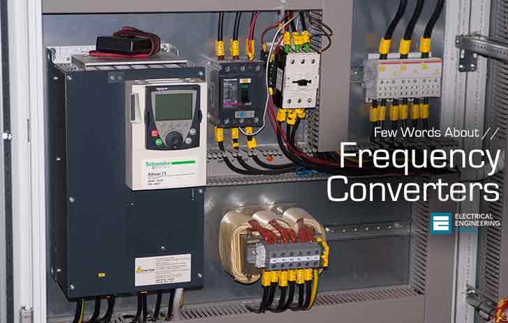
Few Words About Frequency Converters (photo credit: bpa.ru)

Introduction

Since the late 1960’s, frequency converters have undergone extremely rapid changes, largely as a result of the development of microprocessor and semi-conductor technologies and their reduction in prices. However, the basic principles of frequency converters remains the same.

Frequency converters can be divided into four main components:
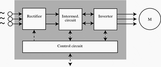
Simplified frequency converter
Figure 1 – Simplified frequency converter

1. Rectifier

The rectifier, which is connected to a single/three-phase AC mains supply and generates a pulsating DC voltage. There are two basic types of rectifiers – controlled and uncontrolled.


2. Intermediate circuit

The intermediate circuit. There are three types:

  1. One, which converts the rectifier voltage into a direct current.
  2. One, which stabilises or smoothes the pulsating DC voltage and places it at the disposal of the inverter.
  3. One, which converts the constant DC voltage of the rectifier to a variable AC voltage.

3. Inverter

The inverter which generates the frequency of the motor voltage. Alternatively, some inverters may also convert the constant DC voltage into a variable AC voltage.


Control circuit

The control circuit electronics, which transmit signals to- and receive signals from the rectifier, the intermediate circuit and the inverter. The parts that are controlled in detail depends on the design of the individual frequency converter (see Figure 2).

What all frequency converters have in common is that the control circuit uses signals to switch the inverter semi-conductors on or off. Frequency converters are divided according to the switching pattern that controls the supply voltage to the motor.

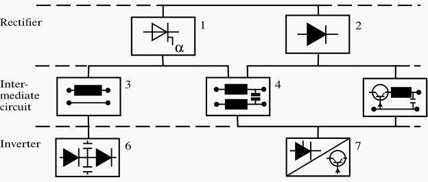
In figure 2, which shows the different design /control principles:

  1. Is a controlled rectifier,
  2. Is an uncontrolled rectifier,
  3. Is a variable DC intermediate circuit,
  4. Is a constant DC voltage intermediate circuit,
  5. Is a variable DC intermediate circuit,
  6. Is a PAM inverter and
  7. PWM inverter.
Different design / control principles of frequency converter
Figure 2 – Different design / control principles of frequency converter

Current Source Inverter: CSI
(1 + 3 + 6)

Pulse-amplitude-modulated converter: PAM
(1 + 4 + 7) (2 + 5 + 7)

Pulse-width-modulated converter: PWM/VVCplus
(2 + 4 + 7)

Direct converters, which do not have an intermediate circuit should also be briefly mentioned for completeness. These converters are used in the Mega-watt power range to generate alow-frequency supply directly from the 50 Hz mains and their maximum output frequency is about 30 Hz.

Resource // Fact Worth Knowing About Frequency Converters – Danfoss

Premium Membership

Get access to premium HV/MV/LV technical articles, electrical engineering guides, research studies and much more! It helps you to shape up your technical skills in your everyday life as an electrical engineer.
More Information
Edvard Csanyi - Author at EEP-Electrical Engineering Portal

Edvard Csanyi

Hi, I'm an electrical engineer, programmer and founder of EEP - Electrical Engineering Portal. I worked twelve years at Schneider Electric in the position of technical support for low- and medium-voltage projects and the design of busbar trunking systems.

I'm highly specialized in the design of LV/MV switchgear and low-voltage, high-power busbar trunking (<6300A) in substations, commercial buildings and industry facilities. I'm also a professional in AutoCAD programming.

Profile: Edvard Csanyi

6 Comments


  1. Rolando
    Oct 18, 2014

    Hello my friends

    I Have a Problem with a 40HP VLT . I changed Powercard and it is runnig Ok . But when the VLT is Stoped The LCP shows an Warning alarm W66 next time the fan cooler is run for abaut 5″ and the w66 is not shows in the LCP.

    Could you helpme please?


    • eugen
      May 29, 2016

      This could indicate that the temperature sensor is defect.


  2. fadymohamed
    Oct 22, 2013

    very helpfull


  3. anbarasan
    Nov 26, 2012

    very gud explination


  4. [email protected]
    Nov 23, 2012

    this panel view just remember me “STARLINGER AUSTRIA” MACHINES PANELS


  5. LaithAlazawy
    Nov 21, 2012

    So Good So Helpful

Leave a Comment

Tell us what you're thinking. We care about your opinion! Please keep in mind that comments are moderated and rel="nofollow" is in use. So, please do not use a spammy keyword or a domain as your name, or it will be deleted. Let's have a professional and meaningful conversation instead. Thanks for dropping by!

  −  7  =  three

Learn How to Design Power Systems

Learn to design LV/MV/HV power systems through professional video courses. Lifetime access. Enjoy learning!

EEP Hand-Crafted Video Courses

Check more than a hundred hand-crafted video courses and learn from experienced engineers. Lifetime access included.
Experience matters. Premium membership gives you an opportunity to study specialized technical articles, online video courses, electrical engineering guides, and papers written by experienced electrical engineers.